SD20-G Series
108
6.1.6 Timing sequence control
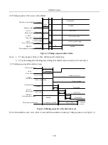
(1) Timing sequence at power on
OFF
ON
Control circuit
power supply
S-RDY
Servo ready is output
More
than 0s
Servo enabled
Dynamic brake
Motor is powered on
Electromagnetic braking
Position, speed and
torque command
No command
command
About
2ms
OFF
Enabled
OFF
OFF
Power off
Power on
Disenable
ON
ON
About 5s
Main circuit
power supply
SON-I
SON -O
So-02
BRAKE
ON
More
than 0s
About 300ms
About 100ms
Enabled
Disenable
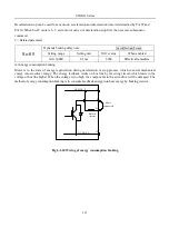
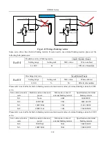
Fig 6-1-6 Sequence control after connecting the power supply
Note:
1. Above diagram is servo drive timing sequence from power-on to receiving command
2. Servo ready is trouble-free output after CPU is reset and main power is connected,.
3. Before servo drive is ready, main power should be connected and all control signal be ignored.
4. When So-07 =0 or 1, after servo on is ready, please wait for at least 100ms before sending control signal,
otherwise control signal might be gnored.
5. When So-07= 2, after servo on is ready, please wait for at least 10ms before sending control signal,
otherwise control signal might be gnored.
Содержание SD20-G Series
Страница 35: ...SD20 G Series 35 M3 structure Fig 3 1 5 Servo drive structure 3...
Страница 36: ...SD20 G Series 36 ML3 structure 118 5 5 7 5 93 297 8 223 118 93 0 5 12 5 7 5 4 M4...
Страница 38: ...SD20 G Series 38 M4 structure Approx mass 10 365 kg Fig 3 1 7 Servo drive structure 5...
Страница 39: ...SD20 G Series 39 M5 structure Approx msaa 11 1Kg Fig 3 1 8 Servo drive structure 6...
Страница 40: ...SD20 G Series 40 M6 structure Approx mass 17 4Kg Fig 3 1 9 Servo drive structure 7...
Страница 182: ...SD20 G Series 182 Fig 6 4 44SD20E Cam internal frameworkdiagram...


