SD20-G Series
152
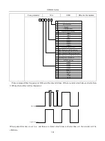
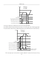
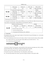
Immediate and the remaining positioning pulses will be cleared. Once the CTRG input contact is activated again
then a new position command will be started according to the selection of input contacts SD0~SD2 Diagram
below shows clear function with incremental encoder.
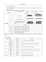
P1
P8
Clear signal
Note: motor accepts
new position command
Absolute move
P1=10 pulses
P8=20 pulses
Position
10
20
-
0
10
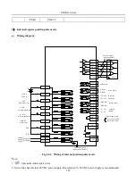
SON-I Enable signal input
Internal register position selection SD0
Internal register position selection SD1
Internal register position selection SD2
Internal register position trigger CTRG
d)
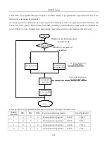
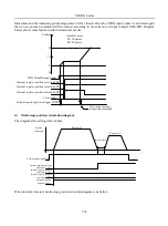
Multi-stage position circulation diagram
The diagram after setting interval time:
t
Position
command
S-ON enabled signal
Internal register position
selection 1
Internal register position
selection 2
Internal register position
selection 3
0
0
0
1
OFF
ON
OFF
Internal register
position trigger
Interval time
Position 1
Position 2
0
When interval time is 0, multi-stage position circulate diagram is as below:
Содержание SD20-G Series
Страница 35: ...SD20 G Series 35 M3 structure Fig 3 1 5 Servo drive structure 3...
Страница 36: ...SD20 G Series 36 ML3 structure 118 5 5 7 5 93 297 8 223 118 93 0 5 12 5 7 5 4 M4...
Страница 38: ...SD20 G Series 38 M4 structure Approx mass 10 365 kg Fig 3 1 7 Servo drive structure 5...
Страница 39: ...SD20 G Series 39 M5 structure Approx msaa 11 1Kg Fig 3 1 8 Servo drive structure 6...
Страница 40: ...SD20 G Series 40 M6 structure Approx mass 17 4Kg Fig 3 1 9 Servo drive structure 7...
Страница 182: ...SD20 G Series 182 Fig 6 4 44SD20E Cam internal frameworkdiagram...


