SD20-G Series
137
6.4.1 Paraemeters setting
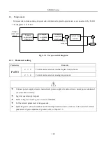
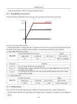
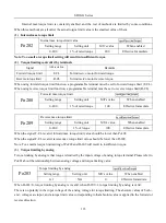
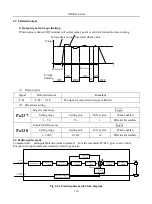
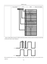
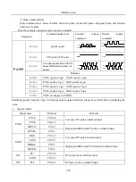
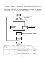
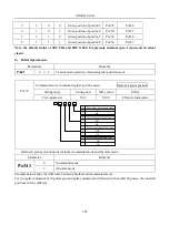
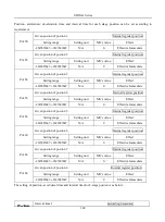
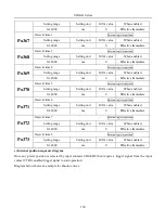
Position pulse mode includes internal register position mode and external position mode, user can select it by Po001.
Parameters
Remarks
Po001
d □ 1
Control mode selection: position pulse mode.
d □ 5
Control mode selection: internal register position mode.
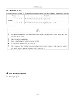
Connect power supply of servo main circuit, power supply of control circuit, motor power cable and
encoder cable correctly.
Jog trial operation by keypad.
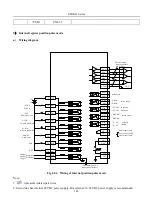
Refer to Fig 6.4.2 and Fig 6.4.6 to connect DI/DO.
Set the related parameters of position mode.
Operating servo drive and make sure the running direction of servo motor is correct, and set related
parameters of gain adjustement, pleaser refer to Chapter 7.3.
1
)
External position pulse mode
a)
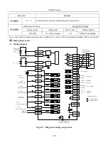
Wiring diagram
Содержание SD20-G Series
Страница 35: ...SD20 G Series 35 M3 structure Fig 3 1 5 Servo drive structure 3...
Страница 36: ...SD20 G Series 36 ML3 structure 118 5 5 7 5 93 297 8 223 118 93 0 5 12 5 7 5 4 M4...
Страница 38: ...SD20 G Series 38 M4 structure Approx mass 10 365 kg Fig 3 1 7 Servo drive structure 5...
Страница 39: ...SD20 G Series 39 M5 structure Approx msaa 11 1Kg Fig 3 1 8 Servo drive structure 6...
Страница 40: ...SD20 G Series 40 M6 structure Approx mass 17 4Kg Fig 3 1 9 Servo drive structure 7...
Страница 182: ...SD20 G Series 182 Fig 6 4 44SD20E Cam internal frameworkdiagram...


