SD20-G Series
65
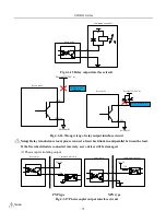
+24V
2.2K
330
Ω
PL2
43
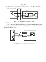
15 /PULS
Servo drive
Command controller
Fig 4.3.6 24V open-collector pulse input interface circuit
c)
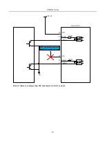
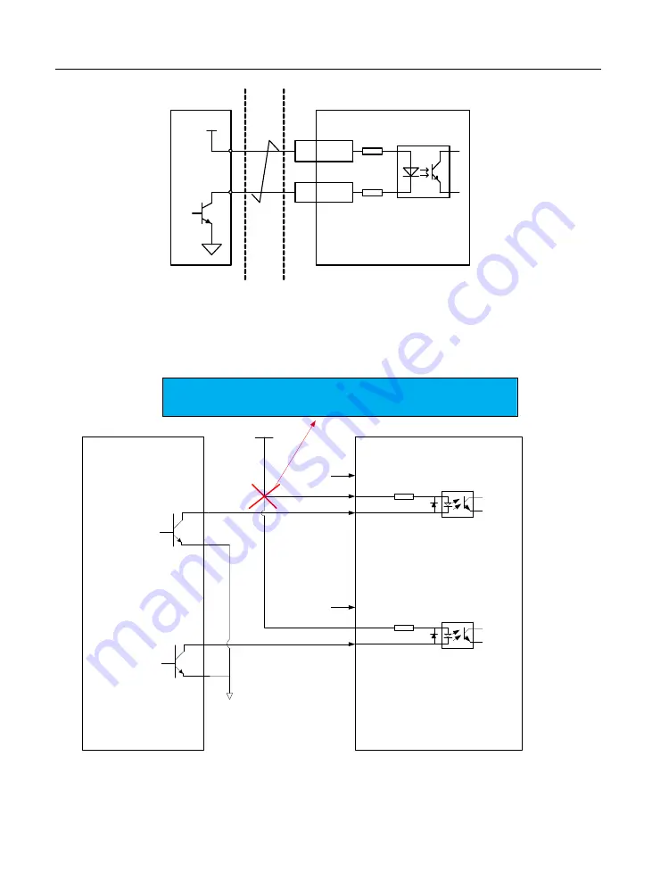
Wrong example:
Error 1: current-limiting resistor is not connected, which leads to port damaged.
Servo drive
+24 V dc
44
43 PL2
PULS
150R
15 /PULS
12
28 PL1
SIGN
150R
27 /SIGN
External 0 V
Two errors are as below:
1. If 24V internal servo drive is not used, please connect it to external resistor.
2. if 24V internal servo drive is used, please connect to 43/28 pin.
Error 2: When SIGN signal is not connected, direction can not be converted.
Содержание SD20-G Series
Страница 35: ...SD20 G Series 35 M3 structure Fig 3 1 5 Servo drive structure 3...
Страница 36: ...SD20 G Series 36 ML3 structure 118 5 5 7 5 93 297 8 223 118 93 0 5 12 5 7 5 4 M4...
Страница 38: ...SD20 G Series 38 M4 structure Approx mass 10 365 kg Fig 3 1 7 Servo drive structure 5...
Страница 39: ...SD20 G Series 39 M5 structure Approx msaa 11 1Kg Fig 3 1 8 Servo drive structure 6...
Страница 40: ...SD20 G Series 40 M6 structure Approx mass 17 4Kg Fig 3 1 9 Servo drive structure 7...
Страница 182: ...SD20 G Series 182 Fig 6 4 44SD20E Cam internal frameworkdiagram...


