SD20-G Series
230
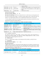
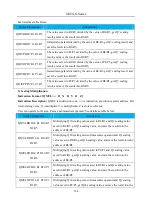
register in R area, the result sends to no.3 register in R area;
SUBDDP D1 P2 R3
R3=D1-P2
Immediate operand subtracted to the value of P register, the
result sends to no.3 register in R area;
SUBDRP R1 P2 R3
R3=R1-P2
The value of R register subtracted to the value of P register, the
result sends to no.3 register in R area;
SUBDPP P1 P2 P3
R3=P1-P2
The values of two registers in P area are subtracted, the result
sends to no.3 register in R area;
(3)
Multiplying Instruction
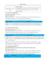
There are 12 multiplying instructions, which are 16-bit and 32-bit multiplication, see details as below:
a)
16-bit Multiplication:
Instruction Format: [MULW□□ X Y Z]
Instruction Description:
MULW is multiplying instruction, □□ is instruction execution register area; X
is multiplier, Y is multiplicand, Z is store result area; The result of instruction execution is Z=X*Y, which
means that the value of register address in X area multiplied to the value of register address in Y area, the
result sends to Z register address; User can operate for R area, P area and immediate operand; See details
as table 8.1.7.
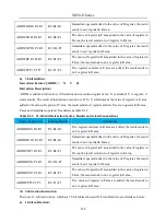
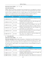
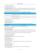
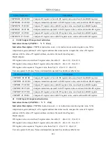
Table 8.1.7 16-bit Multiplying Instruction Syntax, Results and related Annotations
Syntax Expression
Running Results
Annotations
MULWRR R1 R2 R3
R4 R3=R1*R2
Multiplying the value of 2 registers in R area, get the
32-bit result, storing to no.3 and no.4 register in R area
respectively, of which no.4 stores high 16-bit, no.3 stores
low 16-bit.
MULWDR D1 R2 R3
R4 R3=1*R2
Multiplying immediate operand and the value of R
register, get 32-bit result, storing to no.3 and no.4 registers
in R area respectively, of which no.4 stores high 16-bit,
no.3 stores low 16-bit.
MULWPR P1 R2 R3
R4 R3=Po001*R2
Multiplying the values of P register and R register, get the
32-bit result, storing to no.3 and no.4 registers in R area
respectively, of which no.4 stores high 16-bit, no.3 stores
low 16-bit.
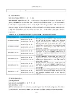
MULWDP D1 P2 R3
R4 R3=1*Po002
Multiplying immediate operand and the value of P
register, get the 32-bit result, storing to no.3 and no.4
registers in R area, of which no.4 stores high 16-bit, no.3
stores low 16-bit.
Содержание SD20-G Series
Страница 35: ...SD20 G Series 35 M3 structure Fig 3 1 5 Servo drive structure 3...
Страница 36: ...SD20 G Series 36 ML3 structure 118 5 5 7 5 93 297 8 223 118 93 0 5 12 5 7 5 4 M4...
Страница 38: ...SD20 G Series 38 M4 structure Approx mass 10 365 kg Fig 3 1 7 Servo drive structure 5...
Страница 39: ...SD20 G Series 39 M5 structure Approx msaa 11 1Kg Fig 3 1 8 Servo drive structure 6...
Страница 40: ...SD20 G Series 40 M6 structure Approx mass 17 4Kg Fig 3 1 9 Servo drive structure 7...
Страница 182: ...SD20 G Series 182 Fig 6 4 44SD20E Cam internal frameworkdiagram...


