


SD20-G Series
183
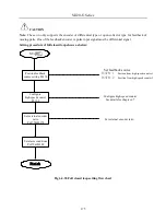
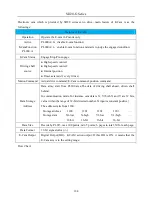
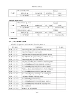
START
Cam point setting
Cam points setting
PL015
Cam initial position
setting
PL001
Refresh cam point
PL017=1
Use PC/PLC to input points?
YES
NO
Conrfirm
command source
Po374.D
Confirm cam condition
PL000.B & PL000.C
Cam occlusive position
setting
PL003
Cam detachment point
& detachment condition
setting
Finish
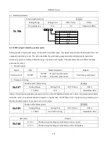
1. PL016 input page no.
2. PL200 area input data
Fig 6.4.45 SD20 servo E-Cam setting flow chart
Содержание SD20-G Series
Страница 35: ...SD20 G Series 35 M3 structure Fig 3 1 5 Servo drive structure 3...
Страница 36: ...SD20 G Series 36 ML3 structure 118 5 5 7 5 93 297 8 223 118 93 0 5 12 5 7 5 4 M4...
Страница 38: ...SD20 G Series 38 M4 structure Approx mass 10 365 kg Fig 3 1 7 Servo drive structure 5...
Страница 39: ...SD20 G Series 39 M5 structure Approx msaa 11 1Kg Fig 3 1 8 Servo drive structure 6...
Страница 40: ...SD20 G Series 40 M6 structure Approx mass 17 4Kg Fig 3 1 9 Servo drive structure 7...
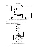
Страница 182: ...SD20 G Series 182 Fig 6 4 44SD20E Cam internal frameworkdiagram...


