SD20-G Series
179
Position Loop
Speed-current
Synchro
Kp
X
X
X
+
-
Position
set
+
Position Loop
Speed-current
Synchro Kp
X
X
X
+
-
+
-
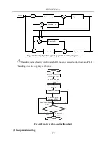
Fig 6.4.41Gantry Synchro typical application wiring diagram
The setting value of gantry synchro gain(Po381) must not exceed position-loop gain(Po301);
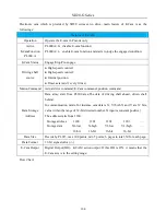
The setting procedure of gantry synchron is:
Start
Interactive connection
of two servo drives
Position feedback
source setting
PL100
Alarm condition
setting
Finish
Synchro gain
setting Po381
Feedback ratio
setting
Smooth running?
YES
Smooth running?
NO
Processing
YES
Satisfied?
NO
Satisfied?
Fig 6.4.42Gantry synchron setting flow chart
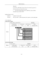
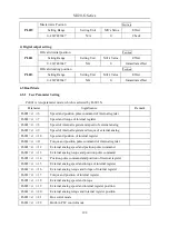
(1) User parameter setting
Содержание SD20-G Series
Страница 35: ...SD20 G Series 35 M3 structure Fig 3 1 5 Servo drive structure 3...
Страница 36: ...SD20 G Series 36 ML3 structure 118 5 5 7 5 93 297 8 223 118 93 0 5 12 5 7 5 4 M4...
Страница 38: ...SD20 G Series 38 M4 structure Approx mass 10 365 kg Fig 3 1 7 Servo drive structure 5...
Страница 39: ...SD20 G Series 39 M5 structure Approx msaa 11 1Kg Fig 3 1 8 Servo drive structure 6...
Страница 40: ...SD20 G Series 40 M6 structure Approx mass 17 4Kg Fig 3 1 9 Servo drive structure 7...
Страница 182: ...SD20 G Series 182 Fig 6 4 44SD20E Cam internal frameworkdiagram...


