SD20-G Series
105
6.1.4 Setting the Overtravel Limit Function
Overtravel limit function prohibit movable machine parts from exceeding the allowable range of motion. A limit
switch, a photoelectric switch or encoder multi-turn number should be adopted for detection.
1.
Hardware overtravel protection function
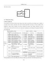
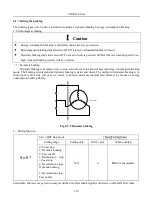
As soon as the servo drive detects the on/off signal from the limit switch, it will force the speed in the present
direction to turn to 0, but it does not work for the speed of opposite direction.
Servo
motor
Reverse rotation direction
Servo
drive
Limit switch
R-INH
F-INH
Forward rotation direction
Limit switch
Fig 6-1-5 Overtravel Limit Function
(1) Input signal
Signal name
Code
Default terminal
Remarks
Forward run prohibited
F-INH
CN3-9
Forbidden servo drive forward run.
Reverse run prohibited
R-INH
CN3-8
Forbidden servo drive reverse run.
(2) Setting related parameter
So-17
Forward run prohibited
Speed Position Torque
Setting range
Setting unit
Mfr’s value
When enabled
0: Prohibited invalid
1: Prohibited valid
N/A
1
Effective Immediate
So-18
Reverse run prohibited
Speed Position Torque
Setting range
Setting unit
Mfr’s value
When enabled
0: Prohibited invalid
1: Prohibited valid
N/A
1
Effective Immediate
(1)Enabled the overtravel signal
When So-17=1, So-18=0 and external control terminals with the function of F-INH and R-INH are allocated, the
overtravel function is enabled. For security, the default setting of So-17 and So-18 are prohibited valid and the
signal input type is common-close contact. So even malfunction occurs, the overtravel protection is still valid.
(2) Disable the overtravel signal
When So-17=0 and So-18=0, the overtravel function is disable. If the input terminals with the function of F-INH
and R-INH are not allocated, the overtravel function is disabled.
(3) Setting the stop torque for overtravel
Po207
Forward/reverse run prohibited
torque
And emergency stop torque
Содержание SD20-G Series
Страница 35: ...SD20 G Series 35 M3 structure Fig 3 1 5 Servo drive structure 3...
Страница 36: ...SD20 G Series 36 ML3 structure 118 5 5 7 5 93 297 8 223 118 93 0 5 12 5 7 5 4 M4...
Страница 38: ...SD20 G Series 38 M4 structure Approx mass 10 365 kg Fig 3 1 7 Servo drive structure 5...
Страница 39: ...SD20 G Series 39 M5 structure Approx msaa 11 1Kg Fig 3 1 8 Servo drive structure 6...
Страница 40: ...SD20 G Series 40 M6 structure Approx mass 17 4Kg Fig 3 1 9 Servo drive structure 7...
Страница 182: ...SD20 G Series 182 Fig 6 4 44SD20E Cam internal frameworkdiagram...


