SD20-G Series
63
4.3.1 Position command input signal and function
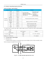
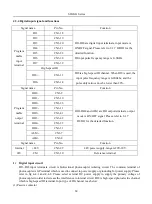
Table 4.3.1 Position command signal
Signal name
Pin No.
Function
Position
command
PULS
CN3-44
Low-speed pulse
command input modes:
differential drive input and
open-collector.
Input pulse types:
Dipulse
A+B phase
orthogonalpulse
CW/CCW pulse
/PULS
CN3-15
SIGN
CN3-12
/SIGN
CN3-27
HPULS+
CN3-4
High-speed pulse position command
HPULS-
CN3-3
HSIGN+
CN3-5
High-speed direction command
HSIGN-
CN3-6
PL1
CN3-28
Pulse direction input (24V)
PL2
CN3-43
Pulse command input (24V)
GND
CN3-24
Signal reference terminal
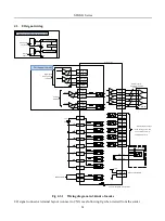
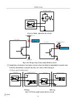
An output circuit for the reference pulse or symbol signal at the host controller can either be differentialdrive
output or OC output.
Pulse
Max frequency
Remarks
Low-speed
Differential
500K
5V or 24V command
OC
200K
High-speed
Differential
4M
5V command
1)
Low-speed pulse command input
a)
Differential drive
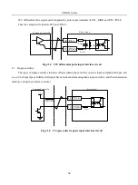
5V differential drive signal can be inputted by pulse input terminals of PULS, /PULS and SIGN, /SIGN.
Take the example of terminals PULS and /PULS.
Servo drive
Command controller
4.7K
330
Ω
PULS
44
15
/PULS
Fig 4.3.3 5V differential pulse input interface circuit
Содержание SD20-G Series
Страница 35: ...SD20 G Series 35 M3 structure Fig 3 1 5 Servo drive structure 3...
Страница 36: ...SD20 G Series 36 ML3 structure 118 5 5 7 5 93 297 8 223 118 93 0 5 12 5 7 5 4 M4...
Страница 38: ...SD20 G Series 38 M4 structure Approx mass 10 365 kg Fig 3 1 7 Servo drive structure 5...
Страница 39: ...SD20 G Series 39 M5 structure Approx msaa 11 1Kg Fig 3 1 8 Servo drive structure 6...
Страница 40: ...SD20 G Series 40 M6 structure Approx mass 17 4Kg Fig 3 1 9 Servo drive structure 7...
Страница 182: ...SD20 G Series 182 Fig 6 4 44SD20E Cam internal frameworkdiagram...


