SD20-G Series
58
4.2 Encoder wiring
Precaution for encoder wire:
1. Make sure servo drive and motor are grounded reliably, otherwise servo drive may have wrong action.
2. Don’t connect encoder cable to NC terminal.
3. User must consider of cable resistance and distributed capacitance to select cable length.Cable resistance may
cause voltage drop, distributed capacitance will lead to signal attenuation,
4. Encoder cable and power cable must be fixed separately, with at least 30cm distance.
5. If encoder cable is not long enough and needs to connet additional cable, cable shielding layer must be also
connected to ensure reliable shielding and grounding.
4.2.1 Absolute encoder connector terminal layout
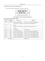
CN2 Encoder Connector Terminal Layout is as shown in figure 4-2-1.
1
2
3
4
5
6
7
8
9
Fig 4.2.1 Absolute Encoder Connector Terminal Layout
Table 4.2.1 Encoder connector terminal
Terminal
code
Terminal
abbreviation
Signal name
Function
CN2- 1
NC
NO CONNECTION
NO CONNECTION
CN2- 2
VCC
+5V power
+5V power
CN2- 3
PS
PG serial signal
Serial signal
CN2- 4
/PS
PG serial signal
Serial signal
CN2- 5
GND
Grounding
Grounding
CN2- 6
CN2- 7
NC
NO CONNECTION
NO CONNECTION
CN2- 8
NC
NO CONNECTION
NO CONNECTION
CN2- 9
NC
NO CONNECTION
NO CONNECTION
HOUSING
——
(
plug cover
)
Note: 4-core 23 bit incremental encoder has the same terminal layout as absolute encloder.
4-core 23 bit incremental encoder and absolute encoder are communication encoder.
Содержание SD20-G Series
Страница 35: ...SD20 G Series 35 M3 structure Fig 3 1 5 Servo drive structure 3...
Страница 36: ...SD20 G Series 36 ML3 structure 118 5 5 7 5 93 297 8 223 118 93 0 5 12 5 7 5 4 M4...
Страница 38: ...SD20 G Series 38 M4 structure Approx mass 10 365 kg Fig 3 1 7 Servo drive structure 5...
Страница 39: ...SD20 G Series 39 M5 structure Approx msaa 11 1Kg Fig 3 1 8 Servo drive structure 6...
Страница 40: ...SD20 G Series 40 M6 structure Approx mass 17 4Kg Fig 3 1 9 Servo drive structure 7...
Страница 182: ...SD20 G Series 182 Fig 6 4 44SD20E Cam internal frameworkdiagram...


