SD20-G Series
145
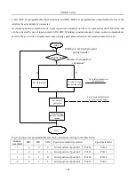
5
1
0
0
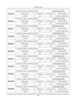
Given postion of postion 5
Po358
Po334
6
1
0
1
Given postion of postion 6
Po360
Po335
7
1
1
0
Given postion of postion 7
Po362
Po336
8
1
1
1
Given postion of postion 8
Po364
Po337
Note: the default status of SD2, SD1 and SD0 is 000, 0 represents terminal open, 1represents terminal
closed.
b)
Related parameters
Parameters
Remarks
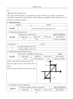
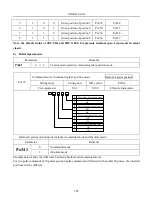
Po001
d □ 5
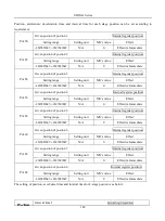
Control mode selection: internal register position mode.
Po375
Command source in internal register position mode Internal register position
Setting range
Setting unit
Mfr’s value
Effect
Four-parameter
N/A
0100
Effective Immediate
b
A
0
1
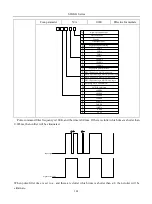
Pulse from Low-speed pulse
B
0
1
C
0
1
D
0
1
Pulse from electronic cam
On
Off
Pulse from high-speed counter1
On
Off
Pulse from internal position
On
Off
On
Off
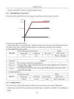
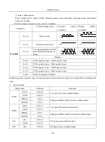
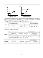
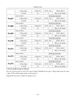
Internal register position mode includes incremental mode and absolute mode.
Parameter
Remarks
Po341
0
Incremental mode
1
Absolute mode
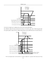
Example below shows the difference between absolute and incremental moves.
For two pulse commands of 10 pulses position pulse command and followed with another 20 pulses, the travelled
positions will be different.
Содержание SD20-G Series
Страница 35: ...SD20 G Series 35 M3 structure Fig 3 1 5 Servo drive structure 3...
Страница 36: ...SD20 G Series 36 ML3 structure 118 5 5 7 5 93 297 8 223 118 93 0 5 12 5 7 5 4 M4...
Страница 38: ...SD20 G Series 38 M4 structure Approx mass 10 365 kg Fig 3 1 7 Servo drive structure 5...
Страница 39: ...SD20 G Series 39 M5 structure Approx msaa 11 1Kg Fig 3 1 8 Servo drive structure 6...
Страница 40: ...SD20 G Series 40 M6 structure Approx mass 17 4Kg Fig 3 1 9 Servo drive structure 7...
Страница 182: ...SD20 G Series 182 Fig 6 4 44SD20E Cam internal frameworkdiagram...

