SD20-G Series
154
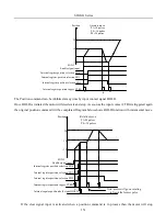
t
0
0
0
1
OFF
ON
OFF
OFF
OFF
0
Position
command
Position 1
Position 1
Position 2
Internal register position
termination signal
Internal register position
hold signal
S-ON enabled signal
Internal register position
selection 1
Internal register position
selection 2
Internal register position
selection 3
Internal register
position trigger
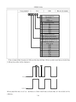
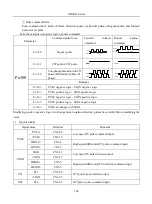
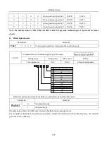
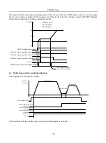
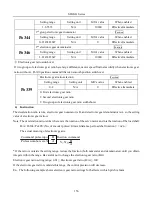
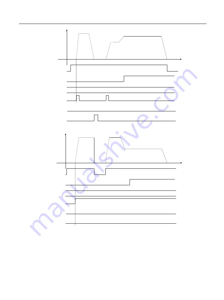
When enabled signal is OFF, the diagram is as below:
t
0
0
0
1
OFF
ON
OFF
OFF
OFF
0
OFF
ON
Position
command
Position 1
Position 1
Position 2
Internal register position
termination signal
Internal register position
hold signal
S-ON enabled signal
Internal register position
selection 1
Internal register position
selection 2
Internal register position
selection 3
Internal register
position trigger
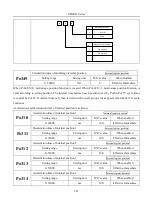
6.4.2 Setting electronic gear
1
)
Electronic gear
At the position control mode, input position command (command unit) is used to set load travel, motor
position command (Encoder unit) is used to set motor travel. Electronic gear ratio is used to set proportional
relation between motor postion command and input position command.
2
)
Procedure for setting the electronic gear ratio
Содержание SD20-G Series
Страница 35: ...SD20 G Series 35 M3 structure Fig 3 1 5 Servo drive structure 3...
Страница 36: ...SD20 G Series 36 ML3 structure 118 5 5 7 5 93 297 8 223 118 93 0 5 12 5 7 5 4 M4...
Страница 38: ...SD20 G Series 38 M4 structure Approx mass 10 365 kg Fig 3 1 7 Servo drive structure 5...
Страница 39: ...SD20 G Series 39 M5 structure Approx msaa 11 1Kg Fig 3 1 8 Servo drive structure 6...
Страница 40: ...SD20 G Series 40 M6 structure Approx mass 17 4Kg Fig 3 1 9 Servo drive structure 7...
Страница 182: ...SD20 G Series 182 Fig 6 4 44SD20E Cam internal frameworkdiagram...


