The number of VLAN interfaces that can be defined for a NetDefendOS installation is limited by
the type of NetDefendOS license. Different hardware models have different licenses and different
limits on VLANs.
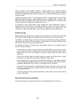
Summary of VLAN Setup
Below are the key steps for setting up a VLAN interface.
1.
Assign a name to the VLAN interface.
2.
Select the physical interface for the VLAN.
3.
Assign a VLAN ID that is unique on the physical interface.
4.
Optionally specify an IP address for the VLAN.
5.
Optionally specify an IP broadcast address for the VLAN.
6.
Create the required route(s) for the VLAN in the appropriate routing table.
7.
Create rules in the IP rule set to allow traffic through on the VLAN interface.
Note: Port Based VLAN
VLANs on the
LAN
interfaces of the NetDefend DFL-260E and DFL-860E models are
configured differently from standard NetDefendOS VLANs. The setup is described fully in
Appendix E, DFL-260E/860E Port Based VLAN
The VLAN processing overhead for these
LAN
interfaces is performed by the switch
fabric that connects these interfaces and not by NetDefendOS. This allows the interfaces
to be divided up into a number of different VLANs. This feature is referred to as
Port
Based VLAN
.
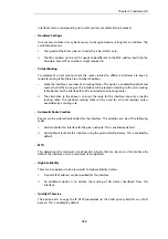
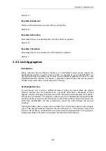
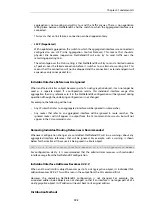
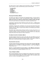
It is important to understand that the administrator should treat a VLAN interface just like a
physical interface in that they require both appropriate IP rules and routes to exist in the
NetDefendOS configuration for traffic to flow through them. For example, if no IP rule with a
particular VLAN interface as the source interface is defined allowing traffic to flow then packets
arriving on that interface will be dropped.
VLAN advanced settings
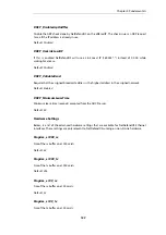
There is a single advanced setting for VLAN:
Unknown VLAN Tags
What to do with VLAN packets tagged with an unknown ID.
Default:
DropLog
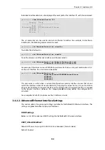
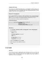
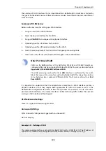
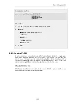
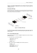
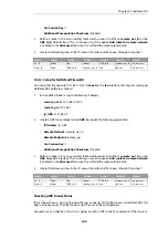
Example 3.21. Defining a VLAN
This simple example defines a virtual LAN called
VLAN10
with a VLAN ID of
10
. The IP address of
the VLAN is assumed to be already defined in the address book as the object
vlan10_ip
.
Chapter 3: Fundamentals
198
Содержание NetDefendOS
Страница 30: ...Figure 1 3 Packet Flow Schematic Part III Chapter 1 NetDefendOS Overview 30 ...
Страница 32: ...Chapter 1 NetDefendOS Overview 32 ...
Страница 144: ...Chapter 2 Management and Maintenance 144 ...
Страница 220: ... Enable DHCP passthrough Enable L2 passthrough for non IP protocols 4 Click OK Chapter 3 Fundamentals 220 ...
Страница 267: ... SourceNetwork lannet DestinationInterface any DestinationNetwork all nets 4 Click OK Chapter 3 Fundamentals 267 ...
Страница 284: ...Chapter 3 Fundamentals 284 ...
Страница 360: ...The ospf command options are fully described in the separate NetDefendOS CLI Reference Guide Chapter 4 Routing 360 ...
Страница 392: ...Chapter 4 Routing 392 ...
Страница 396: ...Web Interface 1 Go to Network Ethernet If1 2 Select Enable DHCP 3 Click OK Chapter 5 DHCP Services 396 ...
Страница 419: ... Host 2001 DB8 1 MAC 00 90 12 13 14 15 5 Click OK Chapter 5 DHCP Services 419 ...
Страница 420: ...Chapter 5 DHCP Services 420 ...
Страница 424: ...2 Now enter Name lan_Access Action Expect Interface lan Network lannet 3 Click OK Chapter 6 Security Mechanisms 424 ...
Страница 573: ...Chapter 6 Security Mechanisms 573 ...
Страница 575: ...This section describes and provides examples of configuring NAT and SAT rules Chapter 7 Address Translation 575 ...
Страница 607: ...Chapter 7 Address Translation 607 ...
Страница 666: ...Chapter 8 User Authentication 666 ...
Страница 775: ...Chapter 9 VPN 775 ...
Страница 819: ...Chapter 10 Traffic Management 819 ...
Страница 842: ...Chapter 11 High Availability 842 ...
Страница 866: ...Default Enabled Chapter 13 Advanced Settings 866 ...
Страница 879: ...Chapter 13 Advanced Settings 879 ...

