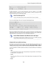
Name
Current value (unit)
---------------
--------------------
SYS Temp
=
44.000 (C)
(x)
CPU Temp
=
41.500 (C)
(x)
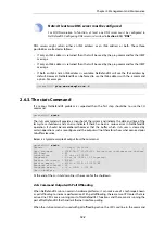
The SYS temperature is for the overall temperature inside the hardware unit. The CPU
temperature relates specifically to the unit's central processor which can be lower than the
overall temperature due to the method of cooling.
Note: The meaning of "(x)"
The "(x)" at the side of each the sensor line, indicates that the sensor is enabled.
The
-verbose
option displays the current values plus the configured ranges:
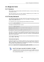
gw-world:/> hwm -a -v
2 sensors available
Poll interval time = 500ms
Name [type][number] = low_limit] current_value [high_limit (unit)
-----------------------------------------------------------------
SYS Temp
[TEMP
][
0] =
44.000]
45.000 [ 0.000 (C)
CPU Temp
[TEMP
][
1] =
42.000]
42.500 [ 0.000 (C)
Time to probe sensors: 2.980000e-05 seconds
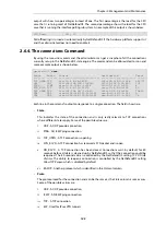
Each physical attribute listed on the left is given a minimum and maximum range within which it
should operate. When the value returned after polling falls outside this range, NetDefendOS
optionally generates a log message that is sent to the configured log servers.
Note: Different hardware has different sensors and ranges
Each hardware model may have a different set of sensors and a different operating
range. The above output and its values are for illustration only.
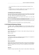
Setting the Minimum and Maximum Range
The minimum and maximum values shown in the output from the
hwm
command are set
through the Web Interface by going to System > Device > Hardware Monitoring > Add and
selecting the hardware parameter to monitor. The desired operating range can then be specified.
A sensor is identified in the Web Interface by specifying a unique combination of the following
parameters:
•
Type
This is the
type
of sensor shown in the CLI output above and is presented as a list of choices in
the Web Interface. For example,
Temp
.
•
Sensor
This is the
number
of the sensor as shown in the CLI output above. For example, the
SYS Temp
number is
0
.
•
Name
Chapter 2: Management and Maintenance
108
Содержание NetDefendOS
Страница 30: ...Figure 1 3 Packet Flow Schematic Part III Chapter 1 NetDefendOS Overview 30 ...
Страница 32: ...Chapter 1 NetDefendOS Overview 32 ...
Страница 144: ...Chapter 2 Management and Maintenance 144 ...
Страница 220: ... Enable DHCP passthrough Enable L2 passthrough for non IP protocols 4 Click OK Chapter 3 Fundamentals 220 ...
Страница 267: ... SourceNetwork lannet DestinationInterface any DestinationNetwork all nets 4 Click OK Chapter 3 Fundamentals 267 ...
Страница 284: ...Chapter 3 Fundamentals 284 ...
Страница 360: ...The ospf command options are fully described in the separate NetDefendOS CLI Reference Guide Chapter 4 Routing 360 ...
Страница 392: ...Chapter 4 Routing 392 ...
Страница 396: ...Web Interface 1 Go to Network Ethernet If1 2 Select Enable DHCP 3 Click OK Chapter 5 DHCP Services 396 ...
Страница 419: ... Host 2001 DB8 1 MAC 00 90 12 13 14 15 5 Click OK Chapter 5 DHCP Services 419 ...
Страница 420: ...Chapter 5 DHCP Services 420 ...
Страница 424: ...2 Now enter Name lan_Access Action Expect Interface lan Network lannet 3 Click OK Chapter 6 Security Mechanisms 424 ...
Страница 573: ...Chapter 6 Security Mechanisms 573 ...
Страница 575: ...This section describes and provides examples of configuring NAT and SAT rules Chapter 7 Address Translation 575 ...
Страница 607: ...Chapter 7 Address Translation 607 ...
Страница 666: ...Chapter 8 User Authentication 666 ...
Страница 775: ...Chapter 9 VPN 775 ...
Страница 819: ...Chapter 10 Traffic Management 819 ...
Страница 842: ...Chapter 11 High Availability 842 ...
Страница 866: ...Default Enabled Chapter 13 Advanced Settings 866 ...
Страница 879: ...Chapter 13 Advanced Settings 879 ...

