


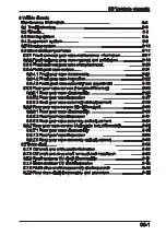


CFMOTO
06-8
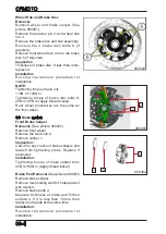
060802
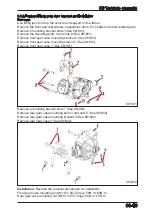
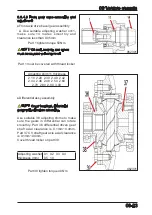
NOTE: Left and right suspension arms have the same method of removal and
installation.
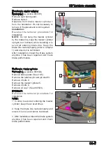
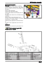
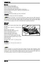
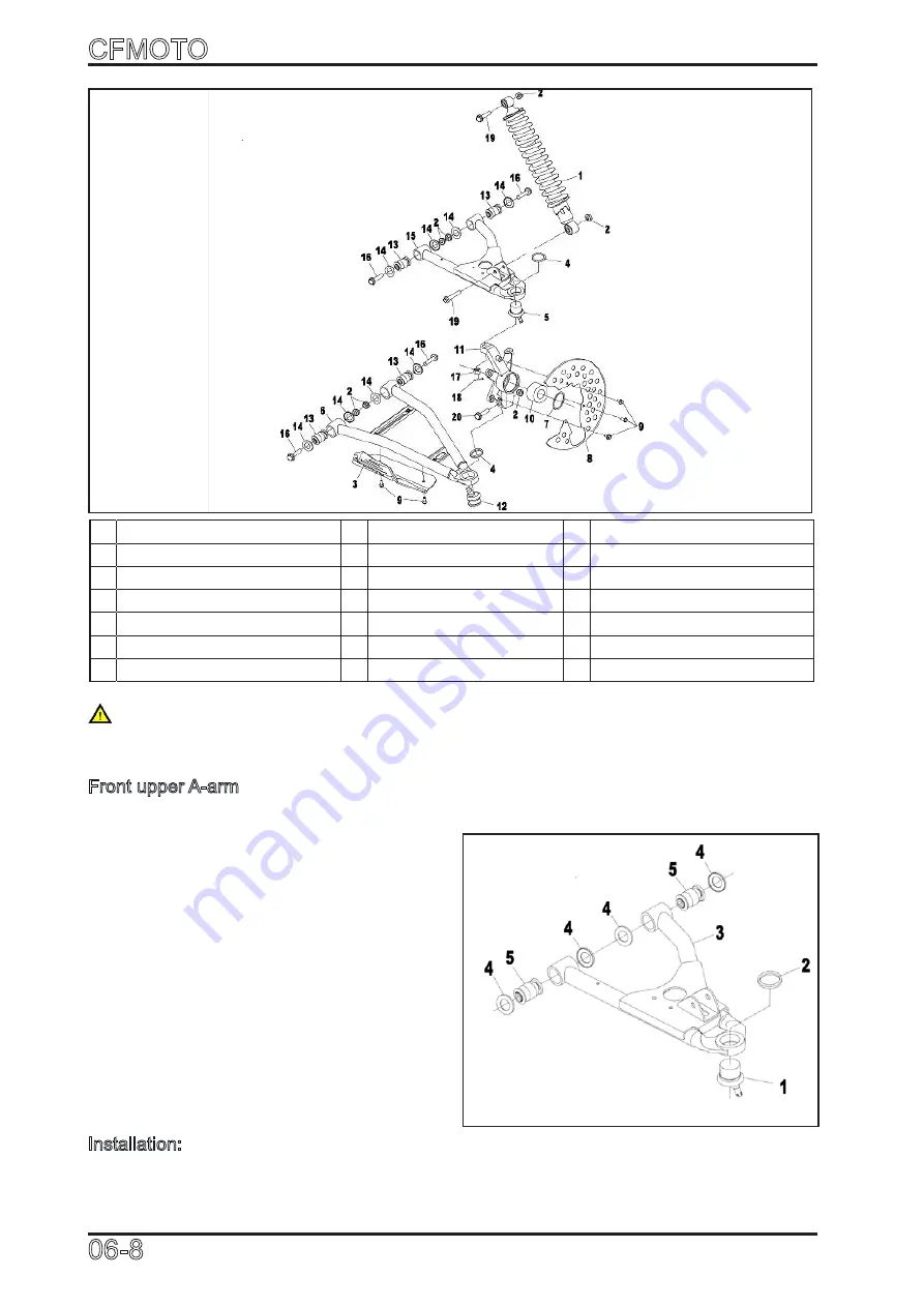
Front upper A-arm
Inspection:
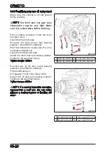
Remove front upper A-arm 3 (See picture
060801, 060802)
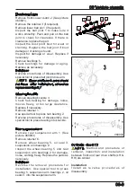
Remove the retainer 2 (if required).
Remove upper ball joint 1 (if required).
Inspect the ball joint 1 to make sure it
works smoothly. Push and pull on the
joint to check for clearance. If there is
clearance, replace the part.
Inspect the dust proof boot for wear or
cracking. Replace the ball joint if boot
damage or cracking is found.
Remove the bushings 5.
Check bushings for damage or aging.
Replace as necessary.
Installation:
Reverse procedures of disassembly. Use
special tool to press ball joint into A-arm.
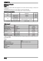
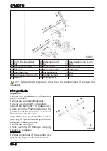
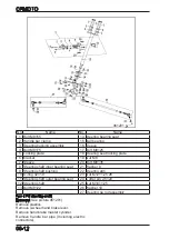
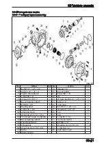
1 Front shock absorber
8 Brake disc guard
15 Upper suspension A-arm
2 Nut
9 Bolt
16 Bolt
3 Suspension guard
10 Hub bearing
17 Groove nut
4 Retainer
11 Steering knuckle
18 Cotter pin
5 Upper ball joint
12 Lower ball joint
19 Bolt
6 Lower suspension A-arm 13 Rubber bushing
20 Bolt
7 Retainer
14 Bushing cover
060801
Содержание CF1000ATR 2018
Страница 1: ...CFMOTO SERVICE MANUAL CF1000AU CF1000ATR CFORCE 1000 ...
Страница 2: ...CFMOTO Edition No 20180817 Edition item CF1000AU 9AY0 WX 01 1 SM 20180817 Website www cfmoto com 1 ...
Страница 81: ...CFMOTO 05 6 5 1 4 EIN Location EIN Location Engine left side Engine right side 050601 050602 ...
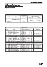
Страница 233: ...CFMOTO 05 158 Material Name P N Page Air filter washer 5 160 5 7 1 Service Material and Exploded View ...
Страница 241: ...CFMOTO 05 166 Waterpump exploded view 648 cylinder locking glue Oil Oil 5699 Sealing glue 10N m 89 lbf in 0516601 ...
Страница 351: ...06 Vehicle chassis 06 41 6 7 3 Front and rear CV shaft disassemble view 064101 064102 ...
Страница 363: ...Appendix A ...
Страница 364: ...Appendix B ...
Страница 365: ...Appendix C ...