


2-39
IM 701210-05E
Explanation of Functions
2
2.4 Setting Waveform Acquisition Conditions and Display Conditions
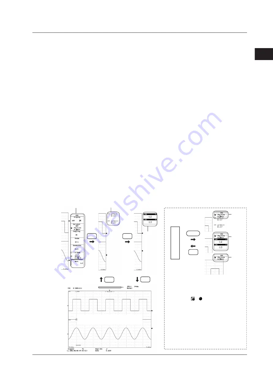
Displaying the Channel Information and Expanding the Waveform Display Area
<Section 8.13>
Pressing the ESC key once when the setup menu is displayed shows the channel
information. The items that are displayed as channel information are as follows:
However, some items may be skipped when the number of displayed channels increases.
• When measuring voltage:
V/div setting, input coupling, probe attenuation (type),
and bandwidth limit.
• When measuring temperature: Temperature/div setting, thermocouple type, and
bandwidth limit.
• When measuring the strain:
µ
STR/div (or [mV/V]/div) setting, measurement range,
and bandwidth limit.
• When measuring acceleration: Acceleration/div setting, gain, input coupling, and bias
setting.
• When measuring frequency:
Value/div setting, measurement mode setting, and
preset setting.
• DSP channel (optional):
Value/div setting and computing equation.
Pressing the ESC key once when the channel information is displayed clears the
channel information and shows the numeric monitor.
Pressing the ESC key once when the numeric monitor is displayed expands the
waveform display area horizontally to cover the entire screen.
In addition, a setup menu of a single parameter may appear at the right corner of the
screen when you press the SELECT key when the channel information or waveform
monitor is displayed or when the waveform display area is expanded. The parameter
controlled by the jog shuttle immediately before the channel information or numeric
monitor was displayed or before the waveform display area was expanded is displayed
here. This setup menu appears when you press the SELECT key only if there are items
that can be controlled by the jog shuttle in the previous menu.
Expand the waveform display area
SELECT
1
1
1
Channel information display
(A)
(C)
(B)
(D)
Numeric
monitor
display
(C)
(B)
(D)
Setup menu
ESC
ESC
ESC
ESC
ESC
1. If there are two parameters in a single setup
menu such as the Z1 Position and Z2 Position
settings of the zoom rate (see section 8.5), the
parameter controlled by the jog shuttle switches
each time you press the SELECT key. The jog
shuttle icon ( or ) is usually white, but it
sometimes turns yellow. Yellow indicates that
two parameters are selected simultaneously
(controlled by the jog shuttle). Taking Z1
Position and Z2 Position as an example,
pressing the SELECT key once selects Z1
Position. Pressing the SELECT key again
selects Z2 Position. Pressing the SELECT key
once more turns the icon yellow and the jog
shuttle controls Z1 Position and Z2 Position. If
you press the SELECT key yet again, the icon
returns to a white color, and the jog shuttle
controls only Z1 Position.