


5-55
IM 701210-05E
Horizontal and Vertical Axes
5
5.20 Setting Logic Waveforms
<For a description of this function, refer to page 2-19.>
Procedure
MEASURE CURSOR
RESET
SELECT
CH
ALL CH
MODE
POSITION
SIMPLE/ENHANCED
ACQ
START/STOP
SETUP
DISPLAY
ZOOM
DUAL
CAPTURE
HISTORY
MATH
1
CH
2
CH
3
CH
4
CH
5
CH
6
CH
7
CH
8
CH
9
CH
10
CH
11
CH
12
CH
13
CH
14
CH
15
CH
16
DELAY
MANUAL TRIG
V/DIV
TIME/DIV
TRIGGER
TRIG D
VERTICAL
HORIZONTAL
CAL
X-Y
SEARCH
7
DSP 1
8
9
DSP 2
6
5
4
1
0
2
3
ENTER
m
DSP 6
DSP 5
LOGIC A
LOGIC B
EVENT
DSP 3
DSP 4
EXP
GO/NO-GO
ACTION
FILE
SHIFT
1.
Press
SHIFT+CH9(LOGIC A)
or
SHIFT+CH10(LOGIC B)
.
Note
For a description of setting the vertical position, see section 5.4. For a description of zooming
vertically by setting the zoom rate, see section 5.8. For a description of setting waveform
labels, see section 8.10.
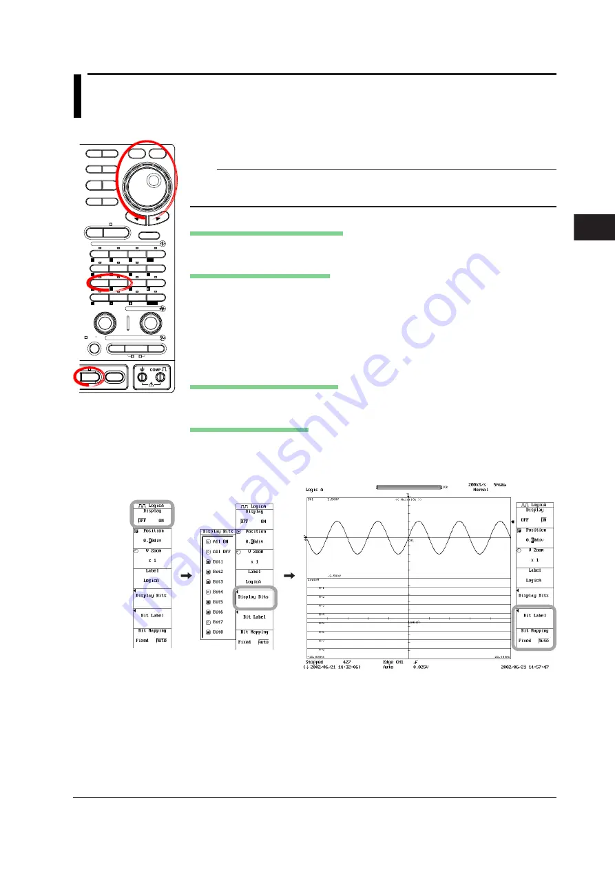
Turning ON/OFF Logic Waveforms
2.
Press the
Display
soft key to select ON or OFF.
Turning ON/OFF the Bit Display
3.
Press the
Display Bits
soft key to display the display ON/OFF setup screen.
4.
Turn the
jog shuttle
to move the cursor to the bit you wish to turn ON.
5.
Press
SELECT
to turn it ON.
You can turn ON all items at once by selecting All ON.
You can turn OFF all items at once by selecting All OFF.
6.
As necessary, repeat steps 4 and 5.
Selecting the Bit Display Position
7.
Press the
Bit Mapping
soft key to select Fixed or Auto.
Setting Labels for Each Bit
8.
Press the
Bit Label
soft key. A setup dialog box opens.
9.
Turn the
jog shuttle
to move the cursor to the bit on which to set the label and
enter the label according to the procedures given in section 4.2.