background image

140

Troubleshooting


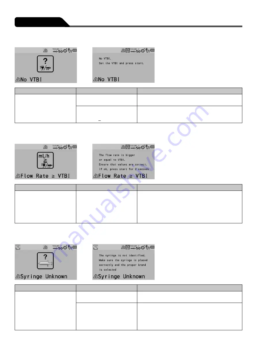
No VTBI alarm


Occurrence

Cause

Action

•  LCD: The No VTBI alarm 

display lights up yellow.

•  Operation indicator: Off.
• Buzzer: Activates.
•  Pump: Remains stopped.

•  The Start switch was pressed 

without having set a VTBI.

•  Set a VTBI and press the Start switch to start solution 

delivery. (See page 57.) 

•  The Start switch was pressed 

with the settings as volume 
delivered > VTBI.

•  Clear the volume delivered (see page 64) or input a 

new value in the VTBI (see page 57) and press the 
Start switch to start solution delivery.

* Only if the VTBI setting function is enabled.


Flow Rate/VTBI Volume Judgment alarm


Occurrence

Cause

Action

•  LCD: The Flow Rate/VTBI 

Volume Judgment alarm 
display lights up yellow.

•  Operation indicator: Off.
• Buzzer: Activates.
•  Pump: Remains stopped.

•  The Start switch was pressed 

with the settings as Flow rate 


VTBI.

•  Check the setting values of the flow rate and VTBI 

(if used). If they are not correct, input correct values 
and press the Start switch to start solution delivery. 
(See pages 55 and 56.) If they are correct, press 
and hold the Start switch for 2 seconds or more to start.

* Only if the VTBI setting function is enabled.


Syringe Barrel Detection alarm


Occurrence

Cause

Action

•  LCD: The Syringe Barrel 

Detection alarm display lights 
up yellow.

•  Operation indicator: Off.
• Buzzer: Activates.
•  Pump: Remains stopped.

•  The syringe in use does not 

match the syringe brand set.

•  Check that the syringe brand setting matches the 

syringe in use.

•  The clamp is still open.
•  The flange is not in the slit.
•  The syringe has not been set 

at the center of the syringe 
detector.

•  Place the syringe correctly. (See pages 32 and 51.)

Summary of Contents for TERUFUSION TE-SS830P

Page 1: ... instruction manual in a convenient location for future reference whenever necessary Read the instructions carefully before using the product and operate in accordance with instructions Perform maintenance and inspections to ensure safe use and extend the life of this product ...

Page 2: ...ate 55 Setting VTBI 56 Setting VTBI Time 57 Priming 58 Inserting a Needle 59 Starting Solution Delivery 60 Stopping Solution Delivery 61 Replacing Syringe to Continue Solution Delivery 62 Turning the Power Off 63 Other Operation Procedures 64 Clearing the Volume Delivered except the TCI mode 64 Standby Function 65 Selecting Dose Mode Drug Library 66 Setting Special Functions 73 Changing Settings o...

Page 3: ...rption distribution and clearance pharmacokinetics and the drug effect on the site of action pharmacodynamics in the human body This product analyzes the drug action by using the PK PD models based on a three compartment model as shown below Mô hình 3 buồng Thuốc vào k12 k13 k21 k31 k1e k10 Vùng ngoại vi V2 Vùng trung tâm V1 Vùng ngoại vi V3 Vùng não Giải phóng ke0 Vùng trung tâm V1 A compartment ...

Page 4: ...nal battery charge and level indicator is displayed on the LCD with 5 bars Wide range of alarm functions The alarm functions include Occlusion alarm Pressure alarm Nearly Empty alarm Slider Displacement alarm Syringe Barrel Detection alarm Syringe Displacement alarm Link Interruption alarm Plunger Displacement alarm Battery alarm Shutdown Notice alarm Power Failure alarm Re alarm Start Reminder No...

Page 5: ...centration page 42 Effect site TCI TCI mode targeting effect site concentration Plasma TCI TCI mode targeting plasma blood concentration Predicted effect site concentration Predicted value of drug concentration in the brain effect site concentration Calculated based on the selected drug model the patient information such as body weight and the target effect site concentration Cet Predicted plasma ...

Page 6: ... Clutch Slit Accepts the flange of a syringe Syringe clamp Fixes the syringe Flange holder Holds the flange of a syringe Plunger detector Slider hook Rear view AC inlet Connects with the AC power cable Tube holder Infrared communication window Communicates with the optional Communication Rack System 1 1 TERUFUSION Communication Rack System Model TE RS800 TERUFUSION Communication Rack System Extens...

Page 7: ...tes the setting rate to set items such as the flow rate See page 73 Display select switch Switches the selected item Flow rate screen Menu screen Press and hold for 2 seconds or more on the flow rate screen to go to the menu screen Back Mute switch Mute the alarm Returns to the previous menu screen In the stop status press and hold for 2 seconds or more to standby In the keypad lock status press a...

Page 8: ... Graph display Displays the change in a time lapse of the predicted concentration Cp or Ce in a graphical format The lines areas are displayed in different colours that are determined by the selected drug 6 Cp Ce display Displays the current value of Cp predicted plasma concentration and Ce predicted effect site concentration 7 Initial infusion display Displays the initial infusion dose and the ti...

Page 9: ...Decrement awakening time Volume delivered Dose rate Flow rate Drug concentration Graph tab Tab display Unit of Y axis plasma effect site concentration Actual time During solution delivery Colour tag Drug name Model Text screen Predicted plasma concentration Cp Predicted effect site concentration Ce Volume delivered Gender Age Height Dose rate Flow rate Text tab Tab display Target concentration Cpt...

Page 10: ...ys the text screen Info tab Displays patient and drug information and the target concentration Cpt or Cet Used when setting the decrement awakening concentration and graph axis Concentration icon Target plasma concentration icon Displays the target plasma concentration Cpt Target effect site concentration icon Displays the target effect site concentration Cet Predicted plasma concentration icon Di...

Page 11: ...e and information for the flow rate mL h etc 2 Volume delivered display Displays the volume delivered Notes Each time you press the Display select switch the selected items rotate as shown below Selected item turns dark blue If not operated for 10 seconds the input area moves to the flow rate display ...

Page 12: ...ars green Approx 8 hours 4 bars green Approx 6 hours 3 bars green Approx 4 5 hours 2 bars green Approx 3 hours 1 bar orange Approx 30 min when the Battery alarm has not been issued In the case of a continuous solution delivery at a flow rate of 5 mL h at temperature of 25 C with new battery after charging for 8 hours or more with the power turned off The battery can be charged to approx 80 in 3 ho...

Page 13: ...ed OFF Mute icon Displays when an alarm is muted Alarm is muted Maintenance icon Displays when the maintenance timer set period has elapsed When the set time period has elapsed For the setting method contact TERUMO trained service technicians Alarm icon Displays when an alarm sounds Background colour red When a high priority alarm sounds Background colour yellow When a medium priority alarm sounds...

Page 14: ...37 Tab display A selected item that can be entered is displayed in dark blue Flow rate tab Used for setting the flow rate Dose rate tab Used for setting the dose rate when the library or the weight mode is selected Volume delivery clear tab Used for clearing volume delivery Info tab Displays the setting information unit weight drug amount solution amount etc Hands On Bolus tab Used for setting the...

Page 15: ...e Drug Library Library is displayed after uploading the Drug Library Occlusion detection pressure 1 to 10 10 kPa 120 kPa Sets the occlusion detection pressure level Keypad lock ON OFF Sets the keypad lock function to ON or OFF Bolus Hands On Bolus Hands Free Bolus Bolus infusion is available with the Purge switch TCI TCI mode only Maximum flow rate Plasma limit Sets the upper limit of flow rate an...

Page 16: ... High Cable insertion or extraction sound 0 Very low 1 Low 2 Medium 3 High Sets the sound volume level Brightness 1 to 5 Dark Bright Sets the brightness level Date and time Year Month Day Hour Minute Sets the date and time Profile Profile range can be set through TERUFUSION Drug Library Manager or TERUFUSION Software Package up to 30 profiles Selects the profile Communication environment Selection...

Page 17: ...FUSION One Touch Pole Clamp TE 877 TE 877 TERUFUSION Drug Library Manager TE SW800 TE SW800BE TERUFUSION Software Package TE SW800 TE SW800PE TERUFUSION Standard Rack System TE RS700 TE RS700N TERUFUSION Communication Rack System TE RS800 TE RS800N TERUFUSION Communication Rack System Extension TE RS811 TE RS811N TERUFUSION One Touch Pole Clamp TE 877 TERUFUSION Drug Library Manager TE SW800 TERUF...

Page 18: ...00 TERUFUSION Communication Rack System TE RS800 Communication box AC power box TERUFUSION Communication Rack System Extension TE RS811 Notes Up to three rack systems can be joined for use To join rack systems contact TERUMO trained service technicians Combination Examples ...

Page 19: ...lution may not be delivered correctly due to rapid infusion caused by displacement of the syringe plunger from the slider hook incorrect detection of the syringe size etc When an occlusion occurs due to tube bend in the infusion line blocked filter blood clot inside the needle or other reasons close the infusion line on the downstream side and eliminate the cause of the occlusion before starting 1...

Page 20: ...l important information on the current TCI mode such as the predicted concentration will be erased When you change any settings make sure those new settings are effective The setting is not applied and the previously set value is restored if no operations are performed during the process for a certain period of time When using a syringe specified sterile syringe for general use for this product en...

Page 21: ...AC power source Do not place this product in an area with obstacles that block the AC power cable from being disconnected No part of this product including the infusion line should be taken into or used in a control area for radiation devices MRI or inside a hyperbaric oxygen therapy room If any part of this product is accidently brought into these environments immediately discontinue use This pro...

Page 22: ...damage to or failure of the LCD or the Operation panel Do not disassemble make alterations including actions that interfere with the functionality or performance such as taping the LCD or a movable part to or repair this product This may result in failure damage or device performance degradation of this product This product should only be used with a sufficient power supply If the power supply is ...

Page 23: ...ctionality or performance of this product and affecting the network system Connection to a network including other devices may cause unpredicted and unacceptable risks for the patient the user or a third person Be sure to identify analyze evaluate and control those risks Subsequent changes to the IT network could introduce new risks and require additional analysis Changes to the IT network include...

Page 24: ...PEN DIPRIVAN 30 17 BD_USA BD PLASTIPAK USA 14 14 17 13 22 16 24 17 30 17 B BR_OMN B BRAUN OMNIFIX 14 17 18 16 22 16 24 17 31 20 B BR_PER B BRAUN ORIGINAL PERFUSOR 21 16 31 38 VACCINE 1 VACCINE 14 17 17 16 22 19 24 20 32 21 P_FERTE PENTAFERTE 15 16 17 17 22 16 26 13 29 18 CHIRANA CHIRANA 30 21 CODAN CODAN 14 14 17 13 23 17 30 20 CODAN_30 CODAN 23 17 CODAN_PR CODAN PERFUSION 30 37 BD_PRECS BD PRECIS...

Page 25: ...lution on the AC inlet and AC power cable 2 There is no damage to the handle rubber protector tube holder and infrared communication window 3 There is no damage or adhered drug solution on the slider slider hook and flange holder including Slit 4 When moving the slider left and right with the clutch pushed it should move smoothly and when it is moved to the left most position while the power is on...

Page 26: ... directions on page 129 Clean periodically even if there is no adhered drug solution 2 The following self check self diagnosis operations should be performed when the power is turned on using the internal battery without a syringe installed 1 The operation indicator lights in green and red alternately 2 The message Self check is displayed on the LCD and the LCD flashes 3 The buzzer sounds 4 The al...

Page 27: ... It should lock in place firmly with an audible click Note For instructions on attaching the IV pole and other parts see page 28 To attach to a horizontal pole Notes The pole clamp can be attached in the vertical direction as shown in the figure Note that the pump cannot be installed in the rack system when the pole clamp is attached in the vertical direction Do not attach the pump in the vertical...

Page 28: ...he pole clamp from the IV pole quickly loosen it slightly by turning the knob in the reverse direction of 3 pull and hold the lever 1 and pull the knob in the reverse direction of 2 Cautions Make sure that pole clamp is firmly fixed to the IV pole and the IV pole is stable When transporting with the unit fixed to the IV pole be aware as the pump may drop or fall due to a floor step slope contact w...

Page 29: ... sub battery failure or low battery If the AC power cable is disconnected or connected with power turned on the buzzer sounds Default setting 0 very low For the changing sound volume see page 105 If the AC power cable is disconnected with power turned on the LCD becomes dim 2 levels of brightness setting When the AC power cable is reconnected the previous brightness is restored Cautions Please ens...

Page 30: ...ged this product may not be able to operate using the internal battery during a power failure etc Time degradation of the internal battery will cause shorter operating hours than indicated by the battery icon on the LCD The battery should be replaced regularly approx every 2 5 to 3 years sub battery 1 to 2 years Since the flashing cross on the battery icon indicates battery failure or replacement ...

Page 31: ...RUMO trained service technicians 1 second or more Press and hold the Power switch for 1 second or more until the TERUMO logo screen is displayed to turn the power on Checks When turning the power on the following occur simultaneously TERUMO logo appears on the display LCD flashes 3 times Operation indicator repeats lighting green and red alternately and then buzzer sounds Operation indicator Notes...

Page 32: ...e sub battery failure The operation indicator is off Setting the Syringe 1 Close the infusion line and attach a syringe filled with solution to it using aseptic technique Caution Only use specified syringes with luer lock for the pump Clamp 1 2 2 Pull the clamp forward and turn Flange Slit 3 Insert the flange into the slit Checks Check the LCD as shown below The flange of the syringe is correctly ...

Page 33: ...nt and then apply light pressure to the slider to push the clutch into position The clutch may click when fitted into the position Clamp 2 1 5 Turn the clamp and gently push it to fix the syringe Check The message Syringe Barrel OK xxx mL is displayed on the LCD and the syringe displacement icon is not displayed xx is the size of the held syringe Display select switch Dial 6 Turn the Dial or press...

Page 34: ...n in by the slider hook If the LCD displays the syringe displacement icon and the buzzer sounds check the syringe has been set correctly and re set if necessary If the syringe is not installed at the correct position the solution delivery cannot be started Even after the syringe is set in the proper position if any fault is observed immediately stop using the product and contact TERUMO trained ser...

Page 35: ...ired TCI mode drug name model and target Plasma targeting Effect site targeting Caution When using the TCI mode be sure to select carefully the appropriate model and target for patients based on the patient characteristics such as age physical trait and medical physical conditions and the latest clinical findings Incorrect settings of model and target may cause significant health hazard to the pat...

Page 36: ...alue and that OK is selected then press the Confirmation switch Note Cpt is displayed instead of Cet when plasma TCI is selected 6 Check The selected drug name model and target are displayed and the syringe displacement icon is not displayed Warning Before using the TCI mode make sure the correct drug name model target and target concentration are displayed Incorrect settings of drug name model ta...

Page 37: ...r sounds every 30 seconds of no operation When the target concentration Cpt or Cet is 0 0 no message is displayed and no buzzer sounds Initial infusion dose Target concentration Cpt or Cet Initial infusion time Prediction lines Notes The target concentration Cpt or Cet can be set within the following range 0 0 to 15 0 μg mL in 0 1 μg mL step Propofol 0 0 to 50 0 ng mL in 0 1 ng mL step Remifentani...

Page 38: ...ch pressed and held the volume delivered display shows the volume purged The upper limit of purge volume is 2 mL The priming function will not work when the syringe pump is stopped by an alarm Warning In the TCI mode perform priming before inserting the intravenous needle to the patient Otherwise it may result in an overdose Cautions TCI mode cannot be used if the syringe is not set properly since...

Page 39: ...infusion due to intravenous needle coming out of vein Periodically check the puncture site Starting Solution Delivery Start switch Operation indicator green flashing Check the setting of target concentration Cpt or Cet and press the Start switch to start solution delivery Notes The buzzer sounds The operation indicator flashes green The displayed values and the graph change in a time lapse Plasma ...

Page 40: ... Cautions When infusing in the TCI mode the following must be observed Do not inject the same drug before starting solution delivery in the TCI mode After ending the TCI mode do not inject to the same patient again in the TCI mode during the period that the drug is assumed to remain in the patient s body Do not inject the same drug from another route during solution delivery in the TCI mode Do not...

Page 41: ...Start to Confirm is displayed on the LCD Start switch Operation indicator green flashing 2 Press the Start switch Notes The target concentration Cpt or Cet is confirmed The buzzer sounds The operation indicator flashes green The line indicating the target concentration Cpt or Cet in the graph is updated Caution If the Start switch is not pressed within approximately 5 seconds the setting is not ap...

Page 42: ...elect DECRMNT CON Note The display returns to the graph screen after 10 seconds of no operation Increases value Dial Decreases value 3 Turn the Dial to change the value of DECRMNT CON Notes The decrement concentration can be set within the range of the following values 0 1 to 15 0 μg mL in 0 1 μg mL step Propofol 0 1 to 50 0 ng mL in 0 1 ng mL step Remifentanil The default setting of the decrement...

Page 43: ...display returns to the graph screen after 5 seconds of no operation While the pump is stopped The display returns to the graph screen after 10 seconds of no operation Be sure to press the Confirmation switch to apply the setting in order to achieve the expected performance Changing Scales The scales of the X axis time and Y axis plasma or effect site concentration in a graph can be changed Display...

Page 44: ...from AUTO 30min 1h 2h 4h 8h and 16h The default setting of the X axis is 30min When AUTO is selected the scale changes stepwise from 30min to 16h with a bar displayed under the number indicating the current scale This will change accordingly the update interval of the graph indicating the predicted plasma concentration Cp and predicted effect site concentration Ce Confirmation switch 5 Press the C...

Page 45: ...ch Replacing the Syringe Solution delivery can be continued by replacing the syringe with a new one Caution To continue the TCI infusion to the same patient do not turn off the power while replacing the syringe with a new one Otherwise all important information on the current TCI mode such as the predicted concentration will be erased 1 To continue solution delivery when the remaining amount in th...

Page 46: ... Perform priming before starting solution delivery to the patient and keep the plunger pushed by the slider Note For details on priming see page Priming on page 38 7 Switch the solution delivery to the patient side and open the infusion line Start switch Operation indicator green flashing 8 Press the Start switch Check The setting of target concentration Cpt or Cet should be correct Notes The buzz...

Page 47: ...elect switch 2 seconds or more 2 Press and hold the Display select switch for 2 seconds or more Note The menu 1 screen End of TCI screen is displayed Confirmation switch 3 Press the Confirmation switch Note The display returns to the graph screen after 10 seconds of no operation Confirmation switch 4 Press the Confirmation switch to select End of TCI Note Confirm end of TCI is displayed on the LCD...

Page 48: ...menu 1 screen Dose mode select screen is displayed To use the mg kg h DIPRIVAN mode see Selecting Dose Mode Weight Mode except TCI Default disabled page 75 Caution Do not end the TCI mode while the TCI mode is in use otherwise all important information on the current TCI mode such as the predicted concentration will be erased ...

Page 49: ...e Power switch is pressed and held without ending the TCI mode a buzzer sounds indicating that the TCI mode is in use The buzzer continues to sound for approx 3 seconds until the power is turned off Warning While in the TCI mode never inject the drug to the same patient again after completion Doing so may result in an overdose Caution Do not turn off the power while the TCI mode is in use otherwis...

Page 50: ...ogo appears on the display LCD flashes 3 times Operation indicator repeats lighting green and red alternately and then buzzer sounds Operation indicator Notes A timer for maintenance can be set in this product When the period set for the maintenance timer is reached a maintenance request is displayed at start up When the request is displayed contact TERUMO trained service technicians When the peri...

Page 51: ...illed with solution to it using aseptic technique Caution Only use specified syringes with luer lock for the pump Clamp 1 2 2 Pull the clamp forward and turn Slit Flange 3 Insert the flange into the slit Checks Check the LCD as shown below The syringe flange is correctly fitted into the slit ...

Page 52: ...nt and then apply light pressure to the slider to push the clutch into position The clutch may click when fitted into the position Clamp 2 1 5 Turn the clamp and gently push it to fix the syringe Check The message Syringe Barrel OK xx mL is displayed on the LCD and the syringe displacement icon is not displayed xx is the size of the held syringe Display select switch Dial 6 Turn the Dial or press ...

Page 53: ...Back Mute switch Display select switch Dial 9 Turn the Dial or press the Display select switch to select the dose mode Notes This section shows an example of selecting mL h for the dose mode For other dose modes see pages 66 and 75 Turning the Dial or pressing the Display select switch moves the white frame Confirmation switch 10 Press the Confirmation switch Note When the Confirmation switch is p...

Page 54: ...ent icon and the buzzer sounds check the syringe has been set correctly and re set if necessary If the syringe is not installed at the correct position the solution delivery cannot be started Even after the syringe is set in the proper position if any fault is observed immediately stop using the product and contact TERUMO trained service technicians When installing a syringe make sure that the syr...

Page 55: ...the initial half turn without changing the value on the display When the value starts to change the buzzer sounds momentarily for confirmation When you stop rotating the Dial and start it again in less than 1 5 seconds the value changes without the initial half turn Rotating the Dial while pressing the Stop switch allows changing the setting at the rate of 100 times When the Dial is turned a line ...

Page 56: ...me calculated from the flow rate and VTBI Start up icon VTBI time Remaining time Notes The VTBI can be set from 0 10 to 9999 00 and Unlimited To set to unlimited turn one rotation or more in the direction of decreasing the Dial when VTBI is 0 In the case of a solution delivery with no setting for the VTBI Unlimited the pump will not stop until the Syringe Empty is issued due to running out drug so...

Page 57: ...ion the setting cannot take a flow rate mL h calculation result outside the flow rate setting range and therefore it should be reconfigured or 0 00 is displayed not allowing solution delivery Keep Vein Open KVO Function When the volume delivered reaches the VTBI the KVO function is activated for the prevention of thrombus formation and thus the flow rate is automatically changed to 0 1 mL h If the...

Page 58: ...of purge volume can be set Contact TERUMO trained service technicians The priming function will not work when the syringe pump is stopped by an alarm Cautions Before inserting an intravenous needle or connecting an infusion line with the connecting site always prime the infusion line by pressing the Purge switch This product may cause harm to a patient due to air injection since it does not have a...

Page 59: ...k The pump is stopped 2 Insert the needle according to the internal hospital procedures Warning This product does not have an alarm function to detect extravascular infusion due to intravenous needle coming out of vein Periodically check the puncture site ...

Page 60: ...Reminder screen yellow and the buzzer sounds Use the standby function see page 65 if you want to temporarily extend the Start Reminder When Solution Delivery Cannot Start The alarm sounds and the following warnings display See page 133 No Flow Rate alarm yellow The flow rate has not been set Set the flow rate and press the Start switch again Cautions If soft and hard limits are not activated befor...

Page 61: ...volume delivered stops increasing O F F Close the three way stopcock 2 Close the infusion line 1 2 Clamp 3 Pull the clamp and then turn Clutch 4 While holding the clutch remove the syringe Warning When removing the syringe installed in this product first close the three way stopcock etc of the infusion line Otherwise excessive infusion siphoning free flow by gravity of the drug solution may occur ...

Page 62: ...displayed on the LCD and then place the syringe Note For details on setting the syringe see page 51 5 Perform priming before starting solution delivery to the patient and keep the plunger pushed by the slider Note For details on priming see page 58 6 Clear the volume delivered as required Note For details on clearing the volume delivered see page 64 Start switch Operation indicator green flashing ...

Page 63: ...e to turn the power off Notes While holding the Power switch the power off buzzer sounds then the LCD displays count down arrows and turns off If the Power switch is pressed and held during solution delivery a buzzer sounds indicating that solution delivery is in progress The buzzer continues to sound for approx 3 seconds until the power is turned off ...

Page 64: ...d Confirmation switch 2 Press the Confirmation switch Note The buzzer sounds the volume delivered is cleared to 0 and the screen returns to the flow rate screen Volume delivered Notes When resuming the solution delivery after the value of the volume delivered is cleared to 0 mL check the flow rate and the VTBI and re set as required To check the volume delivered after clearing the value use the hi...

Page 65: ...the Back Mute switch for 2 seconds or more The standby mode is entered Note The LCD displays the message Stand By Notes The default standby time is 24 hours To change this contact TERUMO trained service technicians the time can be changed to 24 hours or less Turning the Dial or pressing any switch cancels standby mode The standby mode cannot be entered when an alarm has been issued Eliminate the c...

Page 66: ... then the dose mode select Dose display appears The set profile names are displayed next to Library Profiles allow drugs to be classified according to their use and registered in the pump Selecting a profile can limit the available libraries To change the profile see page 112 Check A correct profile name is displayed Dose mode select tab Profile name Confirmation switch 2 Press the Confirmation sw...

Page 67: ...es If clinical advisory is set a message appears With every press of the Confirmation switch the screen changes to the input screen of amount and solution or the input screen of dilution 2 If you want to set by Dilution contact TERUMO trained service technicians 1 Clinical advisory is a function to display a cautionary message about the selected library The message can be registered up to 120 char...

Page 68: ...itch the input area moves to the next one When the Back Mute switch is pressed the parameter input is cancelled and the screen returns to the previous status When all the parameters are input the parameter confirmation screen appears The background colour of the changed parameter value changes on the parameter confirmation screen When the Back Mute switch is pressed on the parameter confirmation s...

Page 69: ...essed and info tab is selected the set information is displayed The following operations can be performed on this display Displaying patient information Displaying drug information Changing parameter values To operate one of these turn the Dial to select the item and press the Confirmation switch When the Back Mute switch is pressed on the parameter confirmation screen the parameter input is cance...

Page 70: ... rates are alternately delivered at regular intervals for the specified number of steps Multi step mode icon The speed of solution delivery increases or decreases at the specified levels Delayed Start mode icon Solution delivery starts after the specified time has elapsed Combination dose mode icon For details contact TERUMO trained service technicians See the dedicated editing software TERUFUSION...

Page 71: ...t reached Override confirmation message is displayed on the LCD Press the Confirmation switch to override the upper or lower limit When the upper or lower limit is overridden the flow rate value turns orange Hard limit If the flow rate reaches the hard limit of the lower limit or the hard limit of the upper limit the This is the hard lower limit or This is the hard upper limit confirmation message...

Page 72: ...shes green The volume delivered increases Even after the setting is completed the TCI mode select screen appears when the power is turned off and on again The amount and solution are re set when the drug library has been changed or the power is turned off The set weight is re set when the power is turned off Change the dose mode from mL h to another mode in drug library during solution delivery ...

Page 73: ...r details see page 88 Volume delivered unit select function In the case of mass system dose mode the unit for volume delivered or VTBI can be changed from volume mL to mass g Alarm melody select function Changes the alarm melody from Pattern 1 to Pattern 2 The default setting is Pattern 1 Night mode setting If the device is left non operated for 30 seconds between 21 00 to 5 00 customizable the br...

Page 74: ...74 Other Operation Procedures Setting item Description of function Set value memory function Saves the current set values e g flow rate VTBI dosage and weight before the power is turned off ...

Page 75: ...isplay select switch 2 seconds or more 1 Press and hold the Display select switch for 2 seconds or more while the solution delivery is stopped Note The menu 1 screen is displayed and then the dose mode select Dose display appears Dose mode select tab Confirmation switch 2 Press the Confirmation switch Note The existing dose mode light blue changes to the selected status dark blue Display select sw...

Page 76: ...mount 0 01 to 999 00 mL Setting range of the dilution Amount 0 01 to 999 00 mg mL Solution If you want to set by Dilution contact TERUMO trained service technicians If the Confirmation switch is pressed after setting the drug amount the input area moves to Solution When the Confirmation switch is pressed after setting the solution amount the input screen of body weight appears When the Back Mute s...

Page 77: ...ressed the flow rate display appears Press the Display select switch to select info tab The setting information appears Parameter values can be changed from the screen displayed by selecting info tab For details about the contents that can be checked from info tab see page 69 Increases value Dial Decreases value 8 Turn the Dial to adjust the dosage For example μg kg min For example mg kg h Flow ra...

Page 78: ...me delivered increases Notes Calculation Formula of Flow Rate Amount mg X 1000 2 RVH UDWH ȝJ NJ PLQ RG ZHLJKW NJ 6ROXWLRQ P Amount mg RVH UDWH PJ NJ K X RG ZHLJKW NJ X 6ROXWLRQ P ORZ UDWH P K X 60 1 1 Coefficient to convert minute min to hour h 2 Coefficient to convert mg to μg Switching the dose unit or re selecting the same dose unit changes the values of flow rate dosage amount solution and vol...

Page 79: ...he display goes to the flow rate screen Method 2 Press the Back Mute switch repeatedly If the setting has not been completed the setting is cancelled and the display goes back to the previous screen If an alarm occurs before pressing the Confirmation switch or the Back Mute switch while setting the menu any changes will return to the settings before the alarm was issued Time before the screen retu...

Page 80: ... review the set value of the occlusion pressure by using the graph of the history of occlusion pressure value as a guide When an Occlusion alarm is issued the occlusion icon may not reach the orange level more than 75 for the following reasons 1 When the bolus reduction function is activated in order to mitigate the occlusion status 2 When the syringe is fully pressed stopped after the Nearly Empt...

Page 81: ...Turn the Dial or press the Display select switch to select occlusion detection pressure Note Turning the Dial or pressing the Display select switch moves the white frame Notes Left side Occlusion detection pressure setting Right side Occlusion history graph In the graph the horizontal axis indicates the time and the vertical axis indicates the occlusion detection pressure Displays a graph of the h...

Page 82: ... Settings on the Menu Confirmation switch 5 Press the Confirmation switch to confirm the selection Note The occlusion icon in the status icon display shows the selected occlusion detection pressure Occlusion icon ...

Page 83: ...he Stop switch is pressed the solution delivery cannot be stopped when the keypad lock is enabled To stop solution delivery first release the keypad lock Display select switch 2 seconds or more 1 Press and hold the Display select switch for 2 seconds or more Note The menu 1 screen is displayed and the icons are ready to be selected Display select switch Dial 2 Turn the Dial or press the Display se...

Page 84: ...he Dial or pressing the Display select switch moves the white frame Confirmation switch 5 Press the Confirmation switch to confirm the selection Checks The keypad lock icon appears in the status icon display The keypad lock message appears when the Dial or a switch other than the Power switch and Start switch is operated Keypad lock icon ...

Page 85: ... The keypad lock icon has disappeared Note Even while the keypad lock is on the Power switch and the Start switch are available Note In the case of a high priority alarm the keypad lock function is automatically switched off However the keypad lock will not be disabled by Start Reminder If the status allows startup the solution delivery can be started while the keypad lock is enabled ...

Page 86: ...lus and Hands Free Bolus Hands On Bolus Display select switch 2 seconds or more 1 Press and hold the Display select switch for 2 seconds or more Notes The menu 1 screen is displayed and the icons are ready to be selected VTBI needs to be set before setting this function if VTBI has been enabled Display select switch Dial 2 Turn the Dial or press the Display select switch to select the bolus tab Bo...

Page 87: ... the bolus volume delivered display is maintained If exceeding 1 5 seconds after the Purge switch has been released the screen returns to the flow rate screen While the Purge switch is pressed the volume delivered display shows the bolus volume delivered When releasing the Purge switch the display shows the sum of the volume delivered The bolus volume delivered is added to the sum of the volume de...

Page 88: ...h for 2 seconds or more Notes The menu 1 screen is displayed and the icons are ready to be selected VTBI needs to be set before setting this function if VTBI has been enabled Display select switch Dial 2 Turn the Dial or press the Display select switch to select the bolus tab Bolus tab Confirmation switch 3 Press the Confirmation switch Display select switch Dial 4 Turn the Dial or press the Displ...

Page 89: ... Mute switch and pressing the Purge switch twice Increases value Dial Decreases value 6 Turn the Dial to set the Bolus VTBI Notes The Bolus VTBI can be set within the range below VTBI 0 01 to 999 00 The Bolus VTBI must be set within the values obtained by subtracting the volume delivered from the VTBI Display select switch 7 Press the Display select switch to select the Bolus VTBI time or the Bolu...

Page 90: ...01 to 1200 00 mL h when using syringe of 50 60 mL Step 0 01 mL h step 0 01 to 10 00 mL h 0 10 mL h step 10 00 to 100 00 mL h 1 00 mL h step 100 00 to 1200 00 mL h The Bolus VTBI time can be set within the range below Bolus VTBI time 00min01s to 60min00s Caution When using the Hands Free Bolus function the setting cannot take a flow rate mL h calculation result outside the flow rate setting range a...

Page 91: ...displays the sum of the amount of bolus and the volume delivered when the VTBI is attained and the bolus ends When bolus infusion during solution delivery is completed solution delivery continues at the flow rate before the bolus infusion A Completion alarm occurs if the volume delivered reaches the VTBI when bolus infusion is used during solution delivery The solution delivery continues at the fl...

Page 92: ...e current setting display turns from light blue to dark blue selected status Display select switch Dial 3 Turn the Dial or press the Display select switch to select the TCI Menu Note Turning the Dial or pressing the Display select switch moves the white frame Confirmation switch 4 Press the Confirmation switch Notes The TCI Menu screen appears The TCI Menu screen can also be displayed if you turn ...

Page 93: ...lues Setting range 0 01 to 999 00 mg kg h Propofol 0 01 to 999 00 μg kg min Remifentanil Step 0 01 step 0 01 to 10 00 0 10 step 10 00 to 100 00 1 00 step 100 00 to 999 00 Confirmation switch 7 Press the Confirmation switch Notes The display returns to the graph screen When the maximum flow rate is changed before starting solution delivery the indications of the initial infusion dose time and the p...

Page 94: ... switch 2 Press the Confirmation switch Note The current setting display turns from light blue to dark blue selected status Display select switch Dial 3 Turn the Dial or press the Display select switch to select the TCI Menu Note Turning the Dial or pressing the Display select switch moves the white frame Confirmation switch 4 Press the Confirmation switch Notes The TCI Menu screen appears The TCI...

Page 95: ...eases value Dial Decreases value 7 Turn the Dial to set the upper limit of plasma concentration Note The upper limit of plasma concentration can be set within the range of 200 to 350 Confirmation switch 8 Press the Confirmation switch Notes The display returns to the graph screen The indications of the initial infusion dose time and the prediction lines in the graph will change accordingly ...

Page 96: ...ate 1 4 Number of steps Dosing time 3 Time Input parameters 1 Dosage rate 1 For the dosage rate range see page 68 When using an advanced dose mode 0 00 can be set for the dosage rate 2 Dosage rate 2 Displays Final Flow Rate 3 Time Displays Time to Final Flow Rate 00h01min to 23h59min 4 Number of steps Displays Steps 1 to 10 steps Delayed Start Mode Solution delivery starts after the specified time...

Page 97: ...lecting the Advanced dose mode on the menu tab of the menu 1 screen The other one is selecting the Advanced Dose Mode displayed below Library in the dose mode select display as described in the following steps If you perform the former procedure go to step 6 Display select switch 2 seconds or more 2 Press and hold the Display select switch for 2 seconds or more Note The menu 1 screen is displayed ...

Page 98: ...ect switch Dial 6 Turn the Dial or press the Display select switch to select the advanced dose mode Note Turning the Dial or pressing the Display select switch moves the white frame Confirmation switch 7 Press the Confirmation switch Note The screen changes to the parameter input display Interval Intermittent Mode Multi step Mode Delayed Start Mode ...

Page 99: ... switch Note The parameter confirmation screen appears Confirmation switch 10 Check the parameter value and that OK is selected press the Confirmation switch Checks The input parameter is correct The screen returns to the flow rate screen and the icon of the selected advanced dose mode is displayed in the lower left of the flow rate display The selected advanced dose mode icon See page 96 Start sw...

Page 100: ...istory If the pump is dropped then a shock record will be created in the history This record will be shown at the top of history Display select switch Back Mute switch 2 seconds or more 1 With the Back Mute switch pressed and held press and hold the Display select switch for 2 seconds or more Note The menu 2 screen is displayed and the icons are ready to be selected Display select switch Dial 2 Tu...

Page 101: ...tes The operation histories are classified by operation status and identified with the colours at the bottom area of LCD as shown in the table below Screen transition As described in Step 4 the Display select switch or Dial can be used to move up and down in the list Pressing the Confirmation switch in the list display displays the detailed history Pressing the Back Mute switch in the detailed his...

Page 102: ...ue Operation history during purge or bolus Hands On Bolus Hands Free Bolus Orange Orange Operation history during standby Display select switch 2 seconds or more 6 Press and hold the Display select switch for 2 seconds or more to return to the flow rate screen Note Set the correct time and date by following the procedure described on page 110 prior to use ...

Page 103: ...first Note The detailed TCI operation history is not available in the TCI mode Display select switch Back Mute switch 2 seconds or more 1 With the Back Mute switch pressed and held press and hold the Display select switch for 2 seconds or more Display select switch Dial 2 Turn the Dial or press the Display select switch to select the TCI history tab TCI history tab Confirmation switch 3 Press the ...

Page 104: ...to move up and down in the list Pressing the Display select switch on the detailed history selects the item in the graph Target concentration Cpt or Cet X axis Y axis Turning the Dial with the item selected displays as follows Target concentration Cpt or Cet Indicates changes in a time lapse X axis Y axis Changes the graph units Pressing the Back Mute switch in the detailed history returns to the ...

Page 105: ...ased on IEC 60601 2 24 2012 EN 60601 2 24 2015 For details refer to IEC 60601 2 24 2012 EN 60601 2 24 2015 Key Operating Volume 0 to 3 1 Cable Insertion Alarm 0 to 3 0 Display select switch Back Mute switch 2 seconds or more 1 With the Back Mute switch pressed and held press and hold the Display select switch for 2 seconds or more Note The menu 2 screen is displayed and the icons are ready to be s...

Page 106: ...y for the item to be changed has appeared Display select switch Dial 6 Turn the Dial or press the Display select switch to select the volume Notes Turning the Dial or pressing the Display select switch moves the white frame When the white frame is placed on a desired level the sound is audible If Step for the alarm volume is selected the volume levels increase in three steps Alarm Volume Key Opera...

Page 107: ...ion switch 7 Press the Confirmation switch to confirm the selection Check The selected volume is displayed Display select switch 2 seconds or more 8 Press and hold the Display select switch for 2 seconds or more to return to the flow rate screen ...

Page 108: ...tch pressed and held press and hold the Display select switch for 2 seconds or more Note The menu 2 screen is displayed and the icons are ready to be selected Display select switch Dial 2 Turn the Dial or press the Display select switch to select the brightness tab Brightness tab Confirmation switch 3 Press the Confirmation switch Note The existing setting light blue changes to the selected status...

Page 109: ...ct switch moves the white frame When the white frame is placed on a desired brightness level the brightness level is shown Confirmation switch 5 Press the Confirmation switch to confirm the selection Check The LCD is displayed with the brightness selected Display select switch 2 seconds or more 6 Press and hold the Display select switch for 2 seconds or more to return to the flow rate screen ...

Page 110: ...d hold the Display select switch for 2 seconds or more Note The menu 2 screen is displayed and the icons are ready to be selected Display select switch Dial 2 Turn the Dial or press the Display select switch to select the date and time tab Date and time tab Confirmation switch 3 Press the Confirmation switch Note Year month date is displayed in dark blue selected Increases value Dial Decreases val...

Page 111: ...Note When the Back Mute switch is pressed the parameter input is cancelled and the screen returns to the previous status Confirmation switch 7 Press the Confirmation switch Notes The time setting is confirmed and the menu 2 screen appears with the icons in the selected status The time is set to 00 seconds Display select switch 2 seconds or more 8 Press and hold the Display select switch for 2 seco...

Page 112: ...the library Display select switch Back Mute switch 2 seconds or more 1 With the Back Mute switch pressed and held press and hold the Display select switch for 2 seconds or more Note The menu 2 screen is displayed and the icons are ready to be selected Display select switch Dial 2 Turn the Dial or press the Display select switch to select the profile tab If no library or profile is registered the p...

Page 113: ...k In Drug library only the drugs set in the selected profile are available See page 66 Note See the dedicated editing software TERUFUSION Drug Library Manager or TERUFUSION Software Package for profile setting and registration of each drug Display select switch 2 seconds or more 6 Press and hold the Display select switch for 2 seconds or more to return to the flow rate screen Note When the AC powe...

Page 114: ...ontact TERUMO trained service technicians Display select switch Back Mute switch 2 seconds or more 1 With the Back Mute switch pressed and held press and hold the Display select switch for 2 seconds or more Note The menu 2 screen is displayed and the icons are ready to be selected Display select switch Dial 2 Turn the Dial or press the Display select switch to select the communication environment ...

Page 115: ... communication environments Notes Turning the Dial or pressing the Display select switch moves the white frame The specified communication environments are restricted depending on the set profile Confirmation switch 6 Press the Confirmation switch to confirm the selection Check The set communication environment No is displayed on screen Communication environment No Display select switch 2 seconds ...

Page 116: ...Turning the Dial or pressing the Display select switch moves the white frame Confirmation switch 3 Press the Confirmation switch Display select switch Dial 4 Turn the Dial or press the Display select switch to select ON OFF Notes The existing setting has been selected dark blue Turning the Dial or pressing the Display select switch moves the white frame Confirmation switch 5 Press the Confirmation...

Page 117: ...117 Changing Settings on the Menu Display select switch 2 seconds or more 6 Press and hold the Display select switch for 2 seconds or more to return to the flow rate screen ...

Page 118: ...n as it is more susceptible to the effect from a radio knife mobile phone radio device defibrillator etc Regularly check that this product is operating normally 4 When using the wireless LAN communication function the effect on other equipment by radio interference should be considered It may affect other equipment 5 When connecting this product with a network the settings of this product and the ...

Page 119: ...en rack system and external device Wireless LAN 1 Use the TERUFUSION Drug Library Manager or TERUFUSION Software Package to set the communication environment in the pump 2 Select a communication environment setting to be used for the pump 3 Enable the wireless LAN of the pump Configuration diagram of wireless LAN Wired LAN Network system Network system TCP Server DHCP server Installed as needed Wi...

Page 120: ...conducting IrDA communication Packet Packet format The following shows the packet format Packet format STX 0x02 Packet data XML format Arbitrary size CRC16 4byte ETX 0x03 Packet data and CRC16 use ASCII code STX 0x02 Fixed Packet data Data division written in XML format For details see this page Packet Packet data CRC16 Error detection calculation for the packet data division The polynomial to be ...

Page 121: ...nt is omitted If element is omitted the pump replies to only the DEVID tag without conditions and sends its own device ID as the reply data CMD tag This tag indicates the command and data to the pump The pump replies to one CMD tag For details on the element commands and data see page 122 The element is converted using Base64 Reply packet data format The following shows the reply packet data forma...

Page 122: ...uence number of the request command received Command The pump sends the same value as that of Command of the request command received SubCommand The pump sends the same value as that of SubCommand of the request command received Execution result When the pump has received a request command and successfully processed it the pump sends 0x00 indicating that execution is successful If the request comm...

Page 123: ...tandby Reserved 0x3 Purge Reserved 0x4 Hands On Bolus Reserved 0x5 Hands Free Bolus Reserved 0x6 0xF Reserved Reserved Reserved 1 Reserved Reserved 1 Reserved Alarm information 3 b0 low order Shutdown Notice alarm b1 Link Interruption alarm b2 Completion alarm b3 Occlusion alarm b4 Syringe Displacement alarm b5 Plunger Displacement alarm b6 Slider Displacement alarm b7 Syringe Barrel Detection ala...

Page 124: ...s 0 Without sound 1 With sound b4 Keypad lock status 0 Not locked 1 Locked b5 Plunger status monitor 0 Set 1 Not set b6 Reserved b7 high order Reserved One bit used for b2 b7 1 indicates active Syringe status 1 0x0 None 0x1 Reserved 0x2 5 mL 0x3 10 mL 0x4 20 mL 0x5 30 mL 0x6 50 60 mL 0x7 0xFF Reserved Flow rate 3 Value of 100 times the set flow rate Volume delivered 3 Value of 100 times the volume...

Page 125: ...sabled 0x0000 Hands Free Bolus flow rate 3 Value of 100 times the flow rate Invalid value when the function is disabled 0x000000 Syringe brand number 1 Brand number of the syringe selected OTCI library version 2 b0 b14 lower Version number Range 0x01 0x7FFF OTCI library unregistered 0x0000 b15 upper Reserved OTCI library number 1 Range 0x01 0x05 When the dose mode other than TCI is selected 0x00 R...

Page 126: ...ration 0 00 to 50 00 0 10 step Range 0x0000 0x1388 When the dose mode other than TCI is selected 0x0000 Predicted awakening time 3 Hour minute second 00 00 00 to 99 59 59 Range 0x000000 0x995959 When the initial flow rate is not set or when the dose mode other than TCI is selected 0x000000 Elapsed time 3 Hour minute second 00 00 00 to 99 59 59 Range 0x000000 0x995959 Before the first solution deli...

Page 127: ...the reply where the device ID is 000100700000001201000001 In this case CRC is D38C 3 Basic operating status request network system pump Data example STX xml version 1 0 REQ DEVID 000100700000001201000001 DEVID CMD AQEAAA CMD REQ A9A4 ETX Note STX 0x02 ETX 0x03 This is an example of the basic operating status request where the device ID is 000100700000001201000001 the sequence number is 01 the comm...

Page 128: ...is present the solution delivery or alarm detection may not operate correctly or may interfere with the normal operation of the clamp part and or movable part of the pole clamp If any drug solution is present clean immediately with a cotton swab Do not wipe with undesignated alcohol other organic solvents such as thinner or povidone iodine Using organic solvent or any antiseptic solution other tha...

Page 129: ...cting use a designated disinfectant The Dial is fixed to the body of the pump with a magnet Remove it following the procedure below before cleaning How to remove the Dial 1 Turn the groove of the Dial to the rear of the device 2 Place a flathead screwdriver in the groove of the Dial and push it outwards 3 Remove the Dial and wipe clean the body and the Dial Grease is applied to the shaft Do not wi...

Page 130: ...Caution Do not soak the pole clamp in water to clean it Pole clamp screw type TERUFUSION One Touch Pole Clamp Optional accessory Cleaning the clamp Wipe with a cotton swab or damp cloth not wet Cleaning the flange slit and the Holding flange Wipe with a damp not wet soft cloth Cleaning the rubber protector and around the rubber protector Wipe with a damp not wet soft cloth Rubber cover Sliding sit...

Page 131: ...ace with a high level of vibration dust mist or corrosive gas Do not expose this product to direct sunlight or ultraviolet irradiation for a long period of time The exterior may experience colour change deformation or deterioration Do not store this product in a place where an environment of atmospheric pressure temperature humidity ventilation salt content or sulfur content may cause an adverse e...

Page 132: ...usage environment the time for replacement for each part may change and replacement of parts other than those scheduled for replacement may also be required Consult TERUMO trained service technicians regarding necessity and replacement The life span of the equipment is at least 6 years in the case of standard use Fuse replacement This product incorporates a fuse inside the structure For replacemen...

Page 133: ...peration indicator flashes red Check the status such as stopped solution delivery Notes The priority of the alarm status is as follows 1 High priority Alarms flashing red on LCD 2 Medium priority Alarms flashing yellow on LCD 3 Low priority Alarms lighting up yellow on LCD Refer to the Alarm icon on page 13 for the alarm priority When more than one alarm sounds at the same time the higher priority...

Page 134: ...134 Troubleshooting Start switch 7 Confirm and restart Check the flow rate VTBI etc and resume the solution delivery ...

Page 135: ...roblem persists contact TERUMO trained service technicians to request repair Syringe Displacement alarm Occurrence Cause Action LCD The Syringe Displacement alarm display flashes red Operation indicator Flashes red Buzzer Activates Pump Stops The syringe has been displaced during solution delivery 1 Replace the syringe correctly See pages 32 and 51 2 Prime the line ensuring that the plunger is kep...

Page 136: ...clusion icon does not turn orange even when an Occlusion alarm is issued The internal pressure of the infusion line has been temporarily mitigated by the bolus reduction function The cause of the occlusion may have been eliminated Ensure that the cause of the occlusion is eliminated before resuming delivery The bolus reduction function is not able to eliminate the cause of occlusion Resuming deliv...

Page 137: ...sed 5 mL syringe 10 mL syringe 20 mL syringe 30 mL syringe 50 60 mL syringe 1 mL h Approx 3 min Approx 11 min Approx 30 min Approx 41 min Approx 64 min 5 mL h Approx 1 0 min Approx 2 5 min Approx 5 0 min Approx 8 5 min Approx 12 0 min Completion alarm Occurrence Cause Action LCD The Completion alarm display flashes red Operation indicator Flashes green Buzzer Activates Pump Switches to the keep ve...

Page 138: ...g a rack system see the instruction manual of the rack system Power Failure alarm Occurrence Cause Action LCD The Power Failure alarm display flashes red Operation indicator Flashes red Buzzer Activates Pump Stops Two of the following causes have occurred No AC power supply Battery failure Sub battery failure or low battery Connect to the AC power supply and charge 8 hours or more with the power t...

Page 139: ...r Activates Pump Remains stopped The Start switch was pressed without having set a flow rate Set a flow rate and press the Start switch to start solution delivery See page 55 The flow rate setting exceeds 150 mL h for 5 mL syringe or 300 mL h for 10 20 or 30 mL syringe Check the value set and re set it to equal or less than 150 mL h or 300 mL h depending on the syringe size used See page 55 Some o...

Page 140: ...n indicator Off Buzzer Activates Pump Remains stopped The Start switch was pressed with the settings as Flow rate VTBI Check the setting values of the flow rate and VTBI if used If they are not correct input correct values and press the Start switch to start solution delivery See pages 55 and 56 If they are correct press and hold the Start switch for 2 seconds or more to start Only if the VTBI set...

Page 141: ...econds or more to set the equipment to standby mode See page 65 Check the setting values for flow rate and VTBI and press the Start switch to start solution delivery See pages 55 and 56 Battery alarm Occurrence Cause Action LCD The Battery alarm display lights up yellow Operation indicator Flashes green during solution delivery or off stopped Buzzer Activates Pump Solution delivery during solution...

Page 142: ... is low If you want to continue the solution delivery replace the syringe See page 62 Re alarm Occurrence Cause Action LCD The respective alarm displays flash light up the flashing light up colours are the same as those at the respective alarms Operation indicator Same as for when the alarms are first activated Buzzer Activates Pump No change to the status Operation was not started within 2 minute...

Page 143: ...ge displacement icon flashes The clamp is still open The flange is not in the slit The syringe is not installed correctly Place the syringe correctly See pages 32 and 51 LCD The Syringe displacement icon flashes The syringe brand setting is incorrect Check that the syringe brand setting matches the brand of the syringe to be set When installing a syringe Slider displacement Occurrence Cause Action...

Page 144: ...nd the battery charge level appear alternately after more than 8 hours of charging The sub battery has deteriorated or is damaged Replace the sub battery Flow rate Occurrence Cause Action Pressing the Start switch does not start solution delivery The infusion line is not open The syringe is not installed correctly 1 Replace the syringe correctly See pages 32 and 51 2 Prime the line ensuring that t...

Page 145: ...on The LCD is dim The equipment is operated using the internal battery The equipment is in the night mode When the night mode is enabled The brightness becomes two levels lower during internal battery operation or night mode operation If it is not the case contact TERUMO trained service technicians The keypad lock icon is displayed The keypad lock is on Press and hold the Back Mute switch for 2 se...

Page 146: ...00 mL h Có thể dùng các bước đặt này khi cài đặt tốc độc bằng núm xoay Giá trị là 0 00 mL h khi bật nguồn Ngưỡng cài đặt VTBI 0 10 đến 100 00 mL bước đặt 0 10 mL 100 00 đến 9999 00 mL bước đặt 1 00 mL Khi cài đặt liều ở đơn vị khối lượng có thể cài đặt đơn vị khối lượng Ngưỡng cài đặt 0 01 ng đến 9999 99 kg Không giới hạn Giá trị là 0 00 mL khi bật nguồn Ngưỡng cài đặt thời gian VTBI 1 phút đến 99...

Page 147: ...ting range 1 s to 60 min 00 s 1 s step Volume delivered display range 0 00 to 10 00 mL 0 01 mL step 10 00 to 100 00 mL 0 10 mL step 100 00 to 9999 00 mL 1 00 mL step When the dose rate is set in mass units the volume is expressed in mass units Volume delivered display range 0 01 ng to 9999 99 kg It will be 0 00 mL when the power is turned on Flow rate accuracy Machine accuracy Within 1 flow rate 1...

Page 148: ...rate setting range can be controlled within the flow rate setting range prescribed for each type of a syringe Values outside the range controlled by this function cannot be set Keypad lock function Disables switch operations However the Start switch the keypad lock function disable operation press and hold the Back Mute switch and the Power switch still function When an alarm is activated the keyp...

Page 149: ...nction Sets the upper limit of the hands on bolus volume Keep Vein Open Function After activation of the Infusion Completion alarm solution delivery is continued at the keep vein open flow rate Keep Vein Open flow rate select function Changes the keep vein open flow rate During start volume delivered clear function except the TCI mode Clears the volume delivered to zero during solution delivery Du...

Page 150: ...tch function A B Switch function A Operations of two pumps are linked When a Completion alarm occurs on the first pump the second pump starts solution delivery Switch function B Interlocks two pumps Starts solution delivery of the first pump and then starts solution delivery of the second pump at the time set in advance or afterwards After solution delivery of the second pump is started each pump ...

Page 151: ...lly charged battery Charging time 8 hours when charged with AC power supply with the power turned off The battery can be charged to approx 80 in 3 hours Sub battery Nickel metal hydride battery for a Power Failure alarm in case of both power supplies are lost Charging time 8 hours when charged with a new battery and AC power supply in ambient temperature of 25 C when the power is off Power consump...

Page 152: ...5 CISPR group classification and class classification are Group 1 and Class A It is also in compliance with the EMC level required by IEC 60601 2 24 2012 EN 60601 2 24 2015 Conformity standard and directive IEC 60601 1 2005 A1 2012 EN 60601 1 2006 A1 2013 IEC 60601 1 2 2007 EN 60601 1 2 2007 IEC 60601 1 2 2014 EN 60601 1 2 2015 IEC 60601 1 6 2010 A1 2013 EN 60601 1 6 2010 A1 2015 IEC 60601 1 8 200...

Page 153: ...TE SS835P02 UK type 100 to 240V TE SS835P03 European type Chế độ cân nặng chỉ có khi được kích hoạt bởi cài đặt bên trong tương ứng Notes Separate setup procedures are required for the product with voltage plug combinations other than listed above If an AC power cable is not included with the pump unit please contact TERUMO trained service technicians to receive the cable suited for your region ...

Page 154: ...e min Flow rate 5 mL h 10 5 0 0 20 40 60 80 100 120 Flow rate mL h Time min 2 Trumpet curve Data for the latter one hour of the 2 hour measurement period is shown with the horizontal axis showing the observation window time minutes and the vertical axis showing the maximum and minimum flow rate error for each observation window The narrower the region enclosed between the top and bottom solid line...

Page 155: ...ringe 50 mL The measured values may vary depending on the test conditions When the 1m extension tube internal volume 1 0 mL is used Note The Occlusion alarm occurrence time with solution delivery at the minimum flow rate 0 01 mL h will be approx 100 times of those at the flow rate 1 mL h Flow rate mL h Occlusion pressure setting value Occlusion pressure Time to activate an Occlusion alarm time min...

Page 156: ...e When using this product in combination with other equipment such as a network system do not place the equipment next to each other or stack them together It may cause malfunctioning due to electromagnetic interference Portable RF communications equipment including peripherals such as antenna cables and external antennas should be used no closer than 30 cm 12 inches to any part of the TERUFUSION ...

Page 157: ...nment Immunity test IEC 60601 test level Compliance level Electromagnetic environment guidance Electrostatic discharge ESD IEC 61000 4 2 6kV contact 8kV air 8kV contact 15kV air Floors should be wood concrete or ceramic tile If floors are covered with synthetic material the relative humidity should be at least 30 Electrical fast transient burst IEC 61000 4 4 2 kV for power supply lines 1 kV for in...

Page 158: ... equipment marked with the following symbol Notes 1 At 80 MHz and 800MHz the higher frequency range applies 2 These guidelines may not apply in all situations Electromagnetic propagation is affected by absorption and reflection from structures objects and people a The ISM industrial scientific and medical bands between 150 KHz and 80 MHz are 6 765 MHz to 6 795 MHz 13 553 MHz to 13 567 MHz 26 957 M...

Page 159: ...800 MHz the separation distance for the higher frequency range applies 2 The ISM industrial scientific and medical bands between 150 kHz and 80 MHz are 6 765 MHz to 6 795 MHz 13 553 MHz to 13 567 MHz 26 957 MHz to 27 283 MHz and 40 66 MHz to 40 70 MHz 3 An additional factor of 10 3 is used in calculating the recommended separation distance for transmitters in the ISM frequency bands between 150 kH...

Page 160: ...ucted RF IEC 61000 4 6 3 Vrms 150 kHz to 80 MHz outside ISM bands 6 Vrms 150 kHz to 80 MHz in ISM bands Power frequency 50 60 Hz magnetic field IEC 61000 4 8 30 A m Voltage dips short interruptions and voltage variations on power supply input lines IEC 61000 4 11 0 UT for 0 5 cycle 0 UT for 1 cycle 70 UT for 25 30 cycles 0 UT for 250 300 cycles Table c Immunity test level to proximity fields from ...

Page 161: ...EC REP Authorized Representative in the European Community Indicates the operation to pull the clamp forward SN Serial number Contents Indicates PE polyethylene plastic bag Japan REF Catalogue number Consult instructions for use Recyclable Lithium ion battery Brazil Date of manufacture Follow instructions for use Contains RoHS 6 Restricted Substances Lithium ion battery China Manufacturer This way...

Page 162: ...adio Equipment Directive 2014 53 EU Hereby TERUMO CORPORATION declares that the radio equipment type TERUFUSION Syringe Pump Type SS3 OTCI is in compliance with Directive 2014 53 EU The full text of the EU declaration of conformity is available at the following internet address http www terumo europe com Other Information ...

Page 163: ...163 Memo ...

Page 164: ...so 2 Edificio Central Park Las Condes Santiago 755 0000 Chile Tel 56 2 2480 9600 Fax 56 2 2480 9608 TERUMO SINGAPORE Pte Ltd 300 Beach Road 33 06 The Concourse Singapore 199555 Tel 65 6 291 3603 Fax 65 6 291 2696 TERUMO THAILAND Co Ltd 1206 12th Floor 54 B B Building Asoke Road Sukhumvit 21 Kwaeng Klongtoeynua Khet Wattana Bangkok 10110 Thailand Tel 66 2 260 7020 Fax 66 2 260 7019 TERUMO VIETNAM M...

Reviews: