

LMV Series
Technical Instructions
LV5-1000
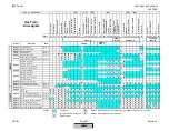
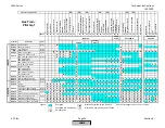
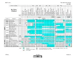
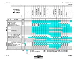
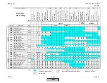
Menu Path
Parameter
Default
Range
Description
51.1
52.2
52.4
LEGEND -
Password Access:
(U)=User, (S)=Service, (O)=OEM, Shaded = Commonly Used, ** = Must Set, X = Has Function, / = Partial Function
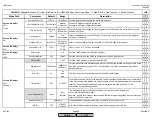
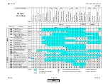
LMV
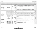
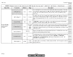
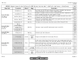
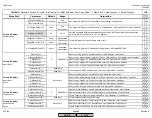
AirTempX60PT1000 (O)
deact
activated
deactivated
Configures LMV5 INPUT X60 for a PT1000 ambient air temperature sensor. Sensor is not
required for O2 trim, but is required for the efficiency calculation. Ambient air temperature
sensor can be wired into terminal X60 of the LMV5 instead of the PLL module if X60 is not
being used for other temperature sensors.
x x
FlueGasTempSens (S)
no sensor
no sensor
Ni1000
Pt1000
Configures the PLL module for the appropriate flue gas temperature sensor. Sensor is not
required for O2 trim, but is required for the efficiency calculation.
x x
MaxTempFlGasGas (S)
MaxTempFlGasOil (S)
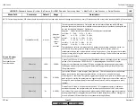
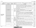
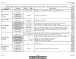
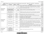
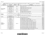
Current O2 Value (U)
This displays the current O2 value. O2 measured on a wet basis.
x x
O2 Setpoint (U)
This displays the O2 setpoint at any operating point. This is the target for the O2 trim.
x x
SupplyAirTemp (U)
This displays the current ambient air temperature.
x x
FlueGasTemp (U)
This displays the current flue gas temperature.
x x
CombEfficiency (U)
This displays the current combustion efficiency. If the O2 sensor is deactivated, this number
will not be displayed. Also, the flue and ambient temperatures are needed for this number to
display.
x x
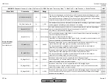
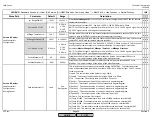
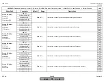
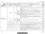
QGO SensorTemp (U)
This displays the current O2 sensor internal temperature. Absolute minimum operating
temperature = 1202 F. Normal operating temperature for QGO20 is approximately 1292 F.
x x
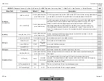
QGO HeatingLoad (U)
This displays the current heating load for the O2 sensor. The PLL serves as the temperature
control for the QGO20 sensor. Maximum heating load is 60%.
x x
QGO Resistance (U)
This measures the resistance of the O2 sensor. As a sensor is used, the resistance increases.
New sensors have a resistance of approximately 5 ohms. A reading of 0 ohms indicates that
a self-test has not been performed after a power off of the LMV5. When this value exceeds
150 ohms, the sensor should be replaced.
x x
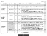
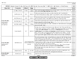
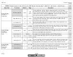
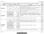
ASN (U)
x x
ProductionDate (U)
x x
SerialNumber (U)
x x
ParamSet Code (U)
x x
ParamSet Vers (U)
x x
Read Only
Read Only
Read Only
Read Only
x x
Params & Display>
O2 Module>
ProductID
Information concerning the currently connected O2 sensor.
Maximum flue temperature setpoint for each fuel. A warning will appear if temperatures
exceed this setting. PLL52 module must have a flue gas sensor wired in for this function.
Params & Display>
O2 Module>
Configuration
752 F
32-1562 F
Params & Display>
O2 Module>
Process Data
Read Only
Read Only
Read Only
Read Only
Read Only
SCC Inc.
Page 41
Section 3
HOME
HOME
P - LIST
Summary of Contents for LMV 5 Series
Page 2: ...Intentionally Left Blank ...
Page 41: ...LMV Series Technical Instructions Document No LV5 1000 SCC Inc Page 7 Section 2 HOME ...
Page 42: ...Technical Instructions LMV Series Document No LV5 1000 Section 2 Page 8 SCC Inc HOME ...
Page 43: ...LMV Series Technical Instructions Document No LV5 1000 SCC Inc Page 9 Section 2 HOME ...
Page 44: ...Technical Instructions LMV Series Document No LV5 1000 Section 2 Page 10 SCC Inc HOME ...
Page 45: ...LMV Series Technical Instructions Document No LV5 1000 SCC Inc Page 11 Section 2 HOME ...
Page 46: ...Technical Instructions LMV Series Document No LV5 1000 Section 2 Page 12 SCC Inc HOME ...
Page 47: ...LMV Series Technical Instructions Document No LV5 1000 SCC Inc Page 13 Section 2 HOME ...
Page 48: ...Technical Instructions LMV Series Document No LV5 1000 Section 2 Page 14 SCC Inc HOME ...
Page 49: ...LMV Series Technical Instructions Document No LV5 1000 SCC Inc Page 15 Section 2 HOME ...
Page 50: ...Technical Instructions LMV Series Document No LV5 1000 Section 2 Page 16 SCC Inc HOME ...
Page 51: ...LMV Series Technical Instructions Document No LV5 1000 SCC Inc Page 17 Section 2 HOME ...
Page 52: ...Technical Instructions LMV Series Document No LV5 1000 Section 2 Page 18 SCC Inc HOME ...
Page 53: ...LMV Series Technical Instructions Document No LV5 1000 SCC Inc Page 19 Section 2 HOME ...
Page 54: ...Technical Instructions LMV Series Document No LV5 1000 Section 2 Page 20 SCC Inc HOME ...
Page 55: ...LMV Series Technical Instructions Document No LV5 1000 SCC Inc Page 21 Section 2 HOME ...
Page 373: ...Intentionally Left Blank ...