
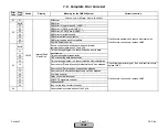
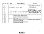
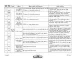
Error
Code
Diag.
Code
Device
Display
Meaning for the LMV5x System
Corrective Action
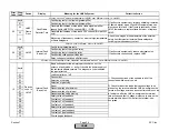
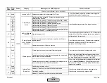
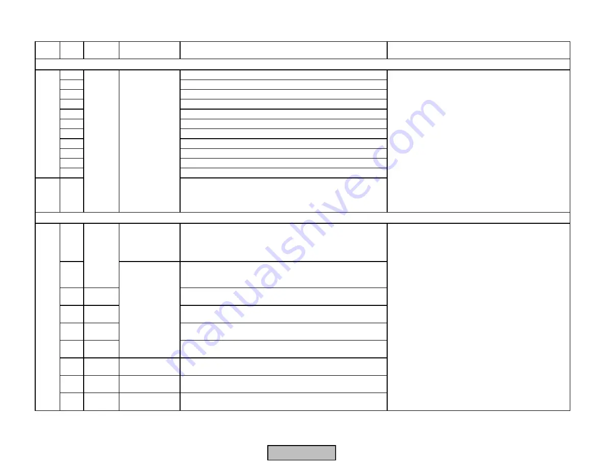
11
Safety chain burner flange
12
Safety relay feedback
13
Pressure switch gas minimum
14
Pressure switch gas maximum
15
Ignition transformer feedback
16
Fan pressure switch
17
Start release oil
18
Heavy oil direct start
19
Load controller open
1A
Load controller closed
1B
Start release gas
11
01
Basic unit has detected a short-circuit in the contact feedback
network
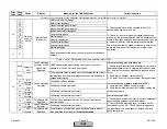
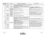
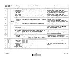
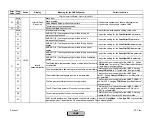
Any #
Fault Positioning
Actuator or Fan
Speed Not
Reached
LMV5 has detected a positioning error on one or several
actuators, or the VSD module if equipped.
01-3F
The diagnostic value is made up of the following faults or their
combinations (the individual diagnostic codes are added up in
hexadecimal format)
01
Air
Actuator
Positioning fault air actuator
02
Active
Fuel
Positioning fault fuel actuator
04
Aux1
Actuator
Positioning fault auxiliary actuator 1
08
Aux2
Actuator
Positioning fault auxiliary actuator 2
10
VSD
module
Fan Speed Not
Reached
The fan in combination with the VSD has not reached the
required speed
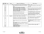
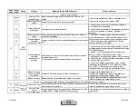
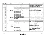
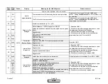
20
Aux3
Actuator
Fault Positioning
Actuator
Positioning fault auxiliary actuator 3
40
VSD
Module
Fan Speed Not
Reached
The difference of actual value and speed setpoint is greater
than permitted by parameter
TolQuickShutdown
If error occurs on one actuator only :
1) Ensure torque requirements of dampers / valves are
less than actuator output. Actuators running over rated
50% duty cycle may have significantly reduced torque
output.
2) Verify that no damper / valve is bound.
3) If 1 and 2 do not solve the problem: replace actuator.
If error occurs on multiple actuators (01-3F) :
1) Verify that the CANBus wiring is correct.
2) Verify that shields (screens) on CANBus cables are
connected properly.
If error occurs on VSD :
1) Check speed sensor on motor for correct installation,
especially gap between sensor and wheel.
2) Check for filters, damping, and / or delays on the
input signal to the VSD. The VSD should respond to
the input signal in a linear fashion. Extend VSD and
LMV5 ramp times.
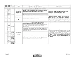
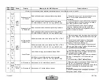
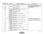
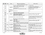
15
Fault Positioning
Actuator
Fault with Connected actuators or VSD
Actuator /
VSD
Control
10
Devices
conn. to
LMV5
Internal Fault
Basic Unit
1) Check connections of the neutrals to all of the
connected switches, valves, etc...
2) Check for inductive loads that cause voltage to be
present on the terminal after the LMV de-energizes the
terminal. If voltage exists on an output terminal, such as
a fuel valve, after the LMV de-energizes the terminal,
this will cause a fault. Voltage must drop to zero on the
terminal within about 10 ms after the terminal is de-
energized.
Fault with devices or wiring connected to the Base Unit (LMV5)
Section 7
Page 25
SCC Inc.
HOMEHOME
HOME
Summary of Contents for LMV 5 Series
Page 2: ...Intentionally Left Blank ...
Page 41: ...LMV Series Technical Instructions Document No LV5 1000 SCC Inc Page 7 Section 2 HOME ...
Page 42: ...Technical Instructions LMV Series Document No LV5 1000 Section 2 Page 8 SCC Inc HOME ...
Page 43: ...LMV Series Technical Instructions Document No LV5 1000 SCC Inc Page 9 Section 2 HOME ...
Page 44: ...Technical Instructions LMV Series Document No LV5 1000 Section 2 Page 10 SCC Inc HOME ...
Page 45: ...LMV Series Technical Instructions Document No LV5 1000 SCC Inc Page 11 Section 2 HOME ...
Page 46: ...Technical Instructions LMV Series Document No LV5 1000 Section 2 Page 12 SCC Inc HOME ...
Page 47: ...LMV Series Technical Instructions Document No LV5 1000 SCC Inc Page 13 Section 2 HOME ...
Page 48: ...Technical Instructions LMV Series Document No LV5 1000 Section 2 Page 14 SCC Inc HOME ...
Page 49: ...LMV Series Technical Instructions Document No LV5 1000 SCC Inc Page 15 Section 2 HOME ...
Page 50: ...Technical Instructions LMV Series Document No LV5 1000 Section 2 Page 16 SCC Inc HOME ...
Page 51: ...LMV Series Technical Instructions Document No LV5 1000 SCC Inc Page 17 Section 2 HOME ...
Page 52: ...Technical Instructions LMV Series Document No LV5 1000 Section 2 Page 18 SCC Inc HOME ...
Page 53: ...LMV Series Technical Instructions Document No LV5 1000 SCC Inc Page 19 Section 2 HOME ...
Page 54: ...Technical Instructions LMV Series Document No LV5 1000 Section 2 Page 20 SCC Inc HOME ...
Page 55: ...LMV Series Technical Instructions Document No LV5 1000 SCC Inc Page 21 Section 2 HOME ...
Page 373: ...Intentionally Left Blank ...