


Technical
Instructions
LMV
Series
Document
No.
LV5
‐
1000
Section
4
Page
24
SCC
Inc.
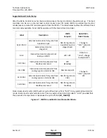
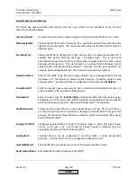
Properly
adjusted
PID
values
will
result
in
the
pressure
/
temperature
staying
within
+/
‐
3%
of
setpoint
without
constantly
changing
the
load
and
modulating
the
actuators.
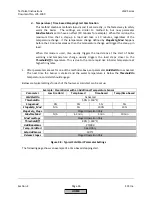
P
‐
Part
(Proportional
Band)
‐
Increases
firing
rate
based
on
how
far
below
setpoint
the
temperature
/
pressure
is.
Smaller
values
cause
a
more
aggressive
P
response
to
a
drop
in
pressure
/
temperature
relative
to
setpoint.
Values
that
are
too
small
will
cause
hunting.
Typical
setting:
10%
to
30%.
I
‐
Part
(Integral)
‐
Serves
to
eliminate
steady
state
"droop"
caused
by
the
proportional
band
setting.
Thus,
this
works
hand
in
hand
with
P
‐
Part
to
bring
the
pressure
/
temperature
up
to
setpoint.
Smaller
values
cause
a
more
aggressive
I
response
(a
setting
of
1
is
most
aggressive).
Values
that
are
too
small
will
cause
overshoot.
Typical
setting:
80
sec
to
300
sec.
A
setting
of
0
deactivates
the
feature,
but
this
is
not
recommended.
D
‐
Part
(Derivative)
‐
Serves
to
eliminate
overshoot,
and
allows
a
more
aggressive
integral
setting.
Larger
values
cause
a
more
aggressive
D
response.
D
‐
Part
is
not
needed
on
many
steam
boilers.
If
needed,
small
values
of
less
than
20
typically
work
well.
A
setting
of
0
deactivates
the
feature.
Large
values
will
typically
cause
hunting.
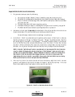
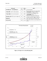
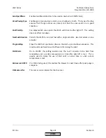
8.
After
the
PID
loop
has
been
adjusted,
it
is
possible
that
the
load
will
still
move
up
and
down
by
a
small
amount
(1
‐
2%
load).
If
this
is
the
case,
adjusting
parameter
MinActuatorStep
may
help
eliminate
this
"micro
‐
hunting".
This
parameter
can
be
found
in
the
following
menu:
Params
&
Display
>
LoadController
>
ControllerParam
MinActuatorStep
is
basically
a
dead
band
for
the
output
of
the
PID
loop.
Typical
setting:
1%
to
4%.
Values
above
5%
could
cause
hunting
issues
in
some
applications.
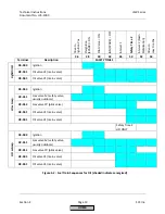
Suggested
Cold
Start
(Thermal
Shock
Protection)
Setup
The
LMV51.1
and
LMV52
have
an
internal
load
control
and
therefore
have
the
ability
to
perform
thermal
shock
protection.
Thermal
shock
protection
only
functions
when
the
LMV5
is
in
an
internal
load
controller
mode,
namely
IntLC,
IntLC
X62,
or
IntLC
Bus
(see
chart
on
previous
pages).
The
cold
start
feature
requires
that
the
temperature
or
pressure
of
the
boiler
is
measured
by
a
sensor
connected
to
the
LMV5.
For
a
hot
water
boiler
(temperature
‐
based
modulation),
the
same
temperature
sensor
that
is
used
for
modulation
must
be
used
for
the
cold
start
feature.
For
a
steam
boiler
(pressure
‐
based
modulation),
a
temperature
sensor
is
also
highly
recommended
for
cold
start.
Temperature
sensors
are
highly
recommended
since
pressure
does
not
always
represent
temperature
in
a
non
‐
firing
steam
boiler,
especially
when
multiple
steam
boilers
are
piped
to
the
same
steam
header.
The
paragraphs
below
will
only
mention
temperature
‐
based
cold
start,
but
the
same
ideas
also
apply
to
pressure
‐
based
cold
start.
HOME
Summary of Contents for LMV 5 Series
Page 2: ...Intentionally Left Blank ...
Page 41: ...LMV Series Technical Instructions Document No LV5 1000 SCC Inc Page 7 Section 2 HOME ...
Page 42: ...Technical Instructions LMV Series Document No LV5 1000 Section 2 Page 8 SCC Inc HOME ...
Page 43: ...LMV Series Technical Instructions Document No LV5 1000 SCC Inc Page 9 Section 2 HOME ...
Page 44: ...Technical Instructions LMV Series Document No LV5 1000 Section 2 Page 10 SCC Inc HOME ...
Page 45: ...LMV Series Technical Instructions Document No LV5 1000 SCC Inc Page 11 Section 2 HOME ...
Page 46: ...Technical Instructions LMV Series Document No LV5 1000 Section 2 Page 12 SCC Inc HOME ...
Page 47: ...LMV Series Technical Instructions Document No LV5 1000 SCC Inc Page 13 Section 2 HOME ...
Page 48: ...Technical Instructions LMV Series Document No LV5 1000 Section 2 Page 14 SCC Inc HOME ...
Page 49: ...LMV Series Technical Instructions Document No LV5 1000 SCC Inc Page 15 Section 2 HOME ...
Page 50: ...Technical Instructions LMV Series Document No LV5 1000 Section 2 Page 16 SCC Inc HOME ...
Page 51: ...LMV Series Technical Instructions Document No LV5 1000 SCC Inc Page 17 Section 2 HOME ...
Page 52: ...Technical Instructions LMV Series Document No LV5 1000 Section 2 Page 18 SCC Inc HOME ...
Page 53: ...LMV Series Technical Instructions Document No LV5 1000 SCC Inc Page 19 Section 2 HOME ...
Page 54: ...Technical Instructions LMV Series Document No LV5 1000 Section 2 Page 20 SCC Inc HOME ...
Page 55: ...LMV Series Technical Instructions Document No LV5 1000 SCC Inc Page 21 Section 2 HOME ...
Page 373: ...Intentionally Left Blank ...