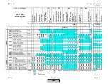


LMV
Series
Technical
Instructions
LV5
‐
1000
SCC
Inc.
Page
49
Section
3
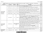
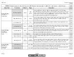
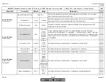
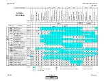
13)
Actuator
position
is
checked
by
using
one
of
three
methods.
The
method
used
depends
upon
the
phase
of
the
sequence.
Position
Required
to
Proceed
means
that
the
actuators
must
achieve
and
hold
a
certain
position
for
the
sequence
to
proceed.
Dynamic
Position
Checking
means
that
the
actuator
is
evaluated
by
a
“time
and
distance
from
target”
algorithm.
The
further
the
actuator
is
away
from
its
target
position,
the
less
time
the
actuator
is
permitted
to
be
in
that
position.
Run
‐
Time
Position
Checking
means
that
the
actuator
is
expected
to
be
at
a
certain
point
in
a
certain
amount
of
time
(based
off
of
the
run
‐
time
of
the
actuator).
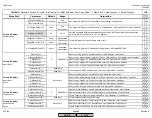
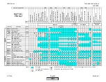
14)
For
direct
spark
oil
fuel
trains,
spark
(ignition)
will
occur
during
prepurge
if
parameter
OilPumpCoupling
is
set
to
Magnetcoupl
and
parameter
IgnOilPumpStart
is
set
to
on
in
Ph22
.
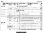
15)
If
parameter
FGR
‐
PS/FCC
is
set
for
PSdeactStby
,
the
status
of
the
FGR
pressure
switch
is
not
checked
in
phase
10
or
12.
The
rest
of
the
sequence
is
the
same
as
setting
this
parameter
to
FGR
‐
PS
.
If
parameter
FGR
‐
PS/FCC
is
set
for
PS
VSD
,
input
X4
‐
01.3
must
be
energized
anytime
the
VSD
speed
is
higher
than
RotSpeed
PS
on
and
de
‐
energized
anytime
the
VSD
speed
is
lower
than
RotSpeed
PS
off
.
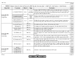
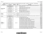
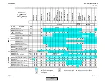
16)
Depending
on
how
parameter
HeavyOilDirStart
is
set,
input
X6
‐
01.3
has
varying
sequences.
If
this
parameter
is
set
for
activ
38/44
,
input
X6
‐
01.3
must
be
energized
in
phase
44.
If
this
parameter
is
set
for
38/44..62
,
input
X6
‐
01.3
must
be
energized
in
phases
44
‐
62.
If
this
parameter
is
set
for
act
21..62
,
input
X6
‐
01.3
must
be
energized
in
phases
21
‐
62.
If
this
parameter
is
set
for
deactivated
,
energizing
input
X6
‐
01.3
has
no
effect.
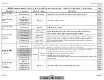
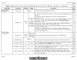
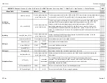
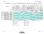
17)
Inputs
X5
‐
03.2
and
X5
‐
03.3
have
many
functions
depending
on
how
parameter
Config
X5
‐
03
is
set.
The
settings
are
as
follows:
LMV5x
std
–
If
parameter
LC_OptgMode
is
set
to
ExtLC
X5
‐
03
,
energizing
X5
‐
03.2
will
decrease
the
firing
rate,
while
energizing
X5
‐
03.3
will
increase
the
firing
rate.
LMV2/3
std
–
If
parameter
LC_OptgMode
is
set
to
ExtLC
X5
‐
03
,
energizing
X5
‐
03.3
will
achieve
stage
2
oil,
while
energizing
X5
‐
03.2
will
achieve
stage
3
oil.
LMV2/3
inv
–
If
parameter
LC_OptgMode
is
set
to
ExtLC
X5
‐
03
,
energizing
X5
‐
03.2
will
achieve
stage
2
oil,
while
energizing
X5
‐
03.3
will
achieve
stage
3
oil.
HOMEHOME
HOME
Summary of Contents for LMV 5 Series
Page 2: ...Intentionally Left Blank ...
Page 41: ...LMV Series Technical Instructions Document No LV5 1000 SCC Inc Page 7 Section 2 HOME ...
Page 42: ...Technical Instructions LMV Series Document No LV5 1000 Section 2 Page 8 SCC Inc HOME ...
Page 43: ...LMV Series Technical Instructions Document No LV5 1000 SCC Inc Page 9 Section 2 HOME ...
Page 44: ...Technical Instructions LMV Series Document No LV5 1000 Section 2 Page 10 SCC Inc HOME ...
Page 45: ...LMV Series Technical Instructions Document No LV5 1000 SCC Inc Page 11 Section 2 HOME ...
Page 46: ...Technical Instructions LMV Series Document No LV5 1000 Section 2 Page 12 SCC Inc HOME ...
Page 47: ...LMV Series Technical Instructions Document No LV5 1000 SCC Inc Page 13 Section 2 HOME ...
Page 48: ...Technical Instructions LMV Series Document No LV5 1000 Section 2 Page 14 SCC Inc HOME ...
Page 49: ...LMV Series Technical Instructions Document No LV5 1000 SCC Inc Page 15 Section 2 HOME ...
Page 50: ...Technical Instructions LMV Series Document No LV5 1000 Section 2 Page 16 SCC Inc HOME ...
Page 51: ...LMV Series Technical Instructions Document No LV5 1000 SCC Inc Page 17 Section 2 HOME ...
Page 52: ...Technical Instructions LMV Series Document No LV5 1000 Section 2 Page 18 SCC Inc HOME ...
Page 53: ...LMV Series Technical Instructions Document No LV5 1000 SCC Inc Page 19 Section 2 HOME ...
Page 54: ...Technical Instructions LMV Series Document No LV5 1000 Section 2 Page 20 SCC Inc HOME ...
Page 55: ...LMV Series Technical Instructions Document No LV5 1000 SCC Inc Page 21 Section 2 HOME ...
Page 373: ...Intentionally Left Blank ...