
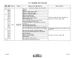
Error
Code
Diag.
Code
Device
Display
Meaning for the LMV5x System
Corrective Action
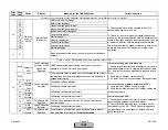
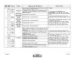
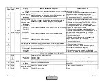
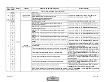
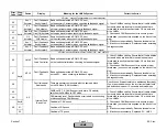
Any #
Basic unit has detected a plausibility fault in the ratio control
system.
The diagnostic code describes the cause of the fault
(see below).
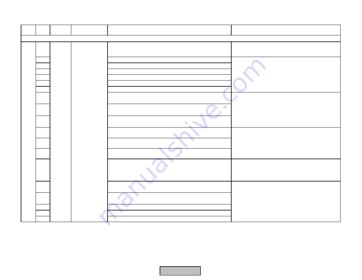
00
Ratio curve of the air actuator is not fully defined
01
Ratio curve of the fuel actuator is not fully defined
02
Ratio curve of auxiliary actuator 1 is not fully defined
03
Ratio curve of auxiliary actuator 2 is not fully defined
04
Ratio curve of auxiliary actuator 3 is not fully defined
05
VSD curve is not fully defined
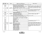
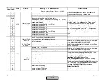
0A
Calculated P-part outside the permissible range
0B
Calculated I-part outside the permissible range
0C
Calculated system delay time outside the permissible range
0D
Calculated O2 setpoint outside the permissible range
0E
Calculated O2 min. value outside the permissible range
0F
Calculated O2 ratio value outside the permissible range
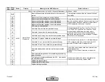
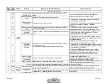
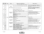
14
Calculated standardized value lies outside the permissible
range
Check if the correct values have been entered for the
standardized values.
Readjust O2 trim control, if required, or repeat the
settings.
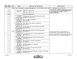
20
With hysteresis compensation: Permissible target positioning
range exceeded
21
The load / point number predefined by the AZLI lies outside
the permissible range
22
Unplausible program branch
23
Unplausible fuel-air ratio phase
40
Unplausible target positions
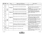
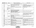
16
LMV5
If fault occurs sporadically, reduce electrical noise.
If fault occurs continuously, replace LMV5.
Internal Fault
Basic Unit
Check parameters (P Low-Fire, I Low-Fire, Tau Low
Fire, P High-Fire, I High-Fire, Tau High-Fire). These
values normally self-set when the delay time is
measured. Check the values of these parameters
against the maximum and minimum ranges. Readjust
O2 control curve if necessary.
The O2 control curve must be 0.1% O2 lower than the
%O2 measured at the ratio control curve, and 0.1%
above the O2 alarm curve. Readjust curves.
Ensure that actuators that are addressed and activated
have their positions defined. Check curve points to see
if correct values have been entered for the actuator or
VSD. Readjust the ratio curve, if required.
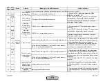
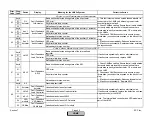
Fault with Base Unit (LMV5) Ratio Control, O2 Trim, VSD
Section 7
Page 26
SCC Inc.
HOME
HOME
Summary of Contents for LMV 5 Series
Page 2: ...Intentionally Left Blank ...
Page 41: ...LMV Series Technical Instructions Document No LV5 1000 SCC Inc Page 7 Section 2 HOME ...
Page 42: ...Technical Instructions LMV Series Document No LV5 1000 Section 2 Page 8 SCC Inc HOME ...
Page 43: ...LMV Series Technical Instructions Document No LV5 1000 SCC Inc Page 9 Section 2 HOME ...
Page 44: ...Technical Instructions LMV Series Document No LV5 1000 Section 2 Page 10 SCC Inc HOME ...
Page 45: ...LMV Series Technical Instructions Document No LV5 1000 SCC Inc Page 11 Section 2 HOME ...
Page 46: ...Technical Instructions LMV Series Document No LV5 1000 Section 2 Page 12 SCC Inc HOME ...
Page 47: ...LMV Series Technical Instructions Document No LV5 1000 SCC Inc Page 13 Section 2 HOME ...
Page 48: ...Technical Instructions LMV Series Document No LV5 1000 Section 2 Page 14 SCC Inc HOME ...
Page 49: ...LMV Series Technical Instructions Document No LV5 1000 SCC Inc Page 15 Section 2 HOME ...
Page 50: ...Technical Instructions LMV Series Document No LV5 1000 Section 2 Page 16 SCC Inc HOME ...
Page 51: ...LMV Series Technical Instructions Document No LV5 1000 SCC Inc Page 17 Section 2 HOME ...
Page 52: ...Technical Instructions LMV Series Document No LV5 1000 Section 2 Page 18 SCC Inc HOME ...
Page 53: ...LMV Series Technical Instructions Document No LV5 1000 SCC Inc Page 19 Section 2 HOME ...
Page 54: ...Technical Instructions LMV Series Document No LV5 1000 Section 2 Page 20 SCC Inc HOME ...
Page 55: ...LMV Series Technical Instructions Document No LV5 1000 SCC Inc Page 21 Section 2 HOME ...
Page 373: ...Intentionally Left Blank ...