


LMV Series
Technical Instructions
Document No. LV5-1000
SCC Inc.
Page 5
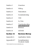
Section 10
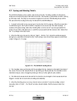
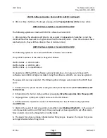
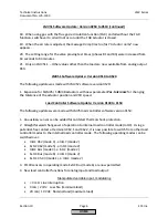
LMV51 Software Update: Version 0250 to 0510 (continued)
2. The flue gas recirculation (FGR) pressure switch input X4-01.3 can be parameterized to not
care in standby mode.
3. New configuration of load controller inputs X5-03.2 and X5-03.3 to act like an LMV3 via
parameter
Config X5-03
.
4. Connection of a pressure switch for valve proving (PS-VP) or POC.
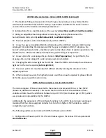
5. Configuration of input X9-03.4 via parameter
GasPressureMin
can be set to
“deact xOGP”
to
deactivate the input when firing oil.
6. Heavy oil direct start input X6-01.3 with more minimum temperature supervision options
(phases 21-62, phases 38-62).
7. Air pressure supervision can be deactivated in standby mode by setting parameter
AirPressureTest
to “
deactInStby
”.
8. Option to adjust the reaction time for loss of flame and the safety time in operation via
parameter
ReacTmeLossFlame
.
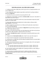
9. Configuration of input X5-03.3 via parameter
Config X5-03
to stop the startup sequence in
phase 36 (driving to ignition position).
10. Using an air actuator and gas control valve, all modulating gas fuel trains can now also be
used for burners with pneumatic or mechanical fuel air ratio control.
11. Parameter
StartPoint Op
available for setting which curve point the LMV5 drives to after
lighting off.
12. Using parameter
DriveLowfire Gas(Oil),
drive to low fire may now start in phase 50.
13. Phases 50 and 52 are skipped if a non-pilot fuel train has been selected.
14. Manual output is unaffected by the load setting when programming the curve parameters,
both via the AZL5 and Modbus.
15. With an external load controller at input X5-03, the integration time of the input signals is
now established as a function of the ramp time.
Examples:
•
For a 30-second ramp time, there will be a load increase of approx. 0.6% per cycle
•
For a 60-second ramp time, there will be a load increase of approx. 0.3% per cycle
16. The minimum actuator step also applies when operating via Modbus or eBus remotely in
order to protect the actuators.
17. Quick shutdown in multistage operation with a variable speed drive (VSD) is only
performed if speed deviations are present that are above the parameterized threshold
TolQuickShutdown
.
HOME
Summary of Contents for LMV 5 Series
Page 2: ...Intentionally Left Blank ...
Page 41: ...LMV Series Technical Instructions Document No LV5 1000 SCC Inc Page 7 Section 2 HOME ...
Page 42: ...Technical Instructions LMV Series Document No LV5 1000 Section 2 Page 8 SCC Inc HOME ...
Page 43: ...LMV Series Technical Instructions Document No LV5 1000 SCC Inc Page 9 Section 2 HOME ...
Page 44: ...Technical Instructions LMV Series Document No LV5 1000 Section 2 Page 10 SCC Inc HOME ...
Page 45: ...LMV Series Technical Instructions Document No LV5 1000 SCC Inc Page 11 Section 2 HOME ...
Page 46: ...Technical Instructions LMV Series Document No LV5 1000 Section 2 Page 12 SCC Inc HOME ...
Page 47: ...LMV Series Technical Instructions Document No LV5 1000 SCC Inc Page 13 Section 2 HOME ...
Page 48: ...Technical Instructions LMV Series Document No LV5 1000 Section 2 Page 14 SCC Inc HOME ...
Page 49: ...LMV Series Technical Instructions Document No LV5 1000 SCC Inc Page 15 Section 2 HOME ...
Page 50: ...Technical Instructions LMV Series Document No LV5 1000 Section 2 Page 16 SCC Inc HOME ...
Page 51: ...LMV Series Technical Instructions Document No LV5 1000 SCC Inc Page 17 Section 2 HOME ...
Page 52: ...Technical Instructions LMV Series Document No LV5 1000 Section 2 Page 18 SCC Inc HOME ...
Page 53: ...LMV Series Technical Instructions Document No LV5 1000 SCC Inc Page 19 Section 2 HOME ...
Page 54: ...Technical Instructions LMV Series Document No LV5 1000 Section 2 Page 20 SCC Inc HOME ...
Page 55: ...LMV Series Technical Instructions Document No LV5 1000 SCC Inc Page 21 Section 2 HOME ...
Page 373: ...Intentionally Left Blank ...