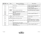

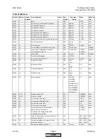
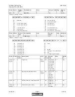
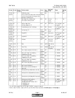
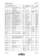
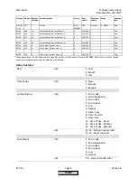

Error
Code
Diag.
Code
Device
Display
Meaning for the LMV5x System
Corrective Action
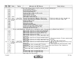
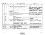
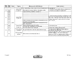
Any #
-
A fault occurred in the O2 module in connection with the flue
gas recirculation
See diagnostic code.
01
Fault with
Feedback from
O2 Module
The flue gas temperature sensor PLL52I input X86 is
selected, but no response is registered on the CAN
Check CANbus and main power wiring to the PLL5.
15
Implausible
supply air
temperature value
Temperature of supply air sensor on PLL52 input X87 is
outside of the valid range (0 to 1472
°
F)
Check wiring of the ambient air sensor connected to
terminal X87. Check ambient air temperature.
16
Implausible flue
gas temperature
value
Value of flue gas temperature sensor on PLL52 input X87 is
outside of the valid range (0 to 1472 °F)
Check wiring of the flue gas temperature sensor
connected to terminal X86. Check flue gas temperature.
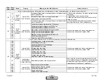
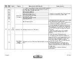
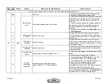
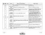
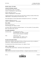
F5
01
Fault with
Feedback from
Load Controller
The Pt1000/Ni1000 on the load controller input X60 is selected,
but no response is registered on the CAN
Check CAN wiring. If fault occurs sporadically, reduce
electrical noise. If fault occurs constantly, replace the
defective unit.
Any #
-
A fault occurred in connection with the flue gas recirculation
function
See diagnostic code.
01
Flue gas
recirculation
automatically
deactivated
The flue gas recirculation function was automatically
deactivated
Check the fault history for the error that happened just
before fault F6 for the cause of the automatic
deactivation.
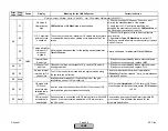
02
Invalid
parameterization
of flue gas
recirculation
operating mode /
flue gas
recirculation
sensor
Invalid parameterization of flue gas recirculation operating
mode / flue gas recirculation sensor in connection with O2
controller / O2 alarm
Set flue gas recirculation operating mode (
FGR-Mode
)
from TCautoDeact to Temp.comp, or set flue gas
recirculation temperature (
FGR-sensor
) to X60
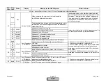
F4
PLL5
F6
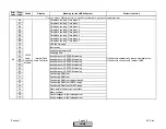
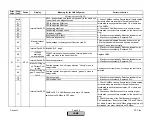
LMV5
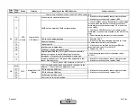
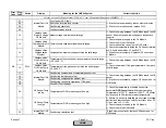
Fault with Base Unit (LMV5) or Connected Components
Section 7
Page 60
SCC Inc.
HOME
HOME
Summary of Contents for LMV 5 Series
Page 2: ...Intentionally Left Blank ...
Page 41: ...LMV Series Technical Instructions Document No LV5 1000 SCC Inc Page 7 Section 2 HOME ...
Page 42: ...Technical Instructions LMV Series Document No LV5 1000 Section 2 Page 8 SCC Inc HOME ...
Page 43: ...LMV Series Technical Instructions Document No LV5 1000 SCC Inc Page 9 Section 2 HOME ...
Page 44: ...Technical Instructions LMV Series Document No LV5 1000 Section 2 Page 10 SCC Inc HOME ...
Page 45: ...LMV Series Technical Instructions Document No LV5 1000 SCC Inc Page 11 Section 2 HOME ...
Page 46: ...Technical Instructions LMV Series Document No LV5 1000 Section 2 Page 12 SCC Inc HOME ...
Page 47: ...LMV Series Technical Instructions Document No LV5 1000 SCC Inc Page 13 Section 2 HOME ...
Page 48: ...Technical Instructions LMV Series Document No LV5 1000 Section 2 Page 14 SCC Inc HOME ...
Page 49: ...LMV Series Technical Instructions Document No LV5 1000 SCC Inc Page 15 Section 2 HOME ...
Page 50: ...Technical Instructions LMV Series Document No LV5 1000 Section 2 Page 16 SCC Inc HOME ...
Page 51: ...LMV Series Technical Instructions Document No LV5 1000 SCC Inc Page 17 Section 2 HOME ...
Page 52: ...Technical Instructions LMV Series Document No LV5 1000 Section 2 Page 18 SCC Inc HOME ...
Page 53: ...LMV Series Technical Instructions Document No LV5 1000 SCC Inc Page 19 Section 2 HOME ...
Page 54: ...Technical Instructions LMV Series Document No LV5 1000 Section 2 Page 20 SCC Inc HOME ...
Page 55: ...LMV Series Technical Instructions Document No LV5 1000 SCC Inc Page 21 Section 2 HOME ...
Page 373: ...Intentionally Left Blank ...