

LMV
Series
Technical
Instructions
Document
No.
LV5
‐
1000
SCC
Inc.
Page
23
Section
6
NumberTauSuspend
‐
The
length
of
time
after
main
flame
light
‐
off
that
is
required
until
an
accurate,
representative
O
2
value
is
read
by
the
O
2
sensor.
Basically,
the
time
it
takes
to
replace
all
of
the
air
in
the
boiler
with
products
of
combustion.
This
parameter
is
a
multiplier
that
is
taken
times
the
delay
time
at
low
fire
(
Tau
Low
‐
Fire
)
to
determine
the
length
of
waiting
time
before
a
representative
O
2
value
is
measured
and
the
O
2
trim
can
engage.
If
Tau
Low
‐
Fire
was
read
to
be
5
seconds
during
O
2
Control
Curve
commissioning,
and
NumberTauSuspend
is
set
to
10,
then
the
O
2
trim
would
engage
50
seconds
after
main
flame
light
‐
off.
A
setting
of
10
will
work
for
almost
all
applications,
and
will
be
conservative
for
most.
Higher
numbers
(more
waiting
time)
are
more
conservative
and
lower
numbers
are
less
conservative.
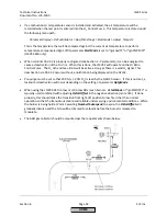
Menu
path:
Params
&
Display
>
O2Contr/Alarm
>
Gas
Settings
>
Startmode
Startmode
‐
This
determines
how
the
burner
transitions
from
light
‐
off
to
engaging
the
O
2
trim.
Two
of
the
modes,
“Ign
Load
TC”
and
“IgnPtWithTC”,
require
a
combustion
air
temperature
sensor.
Immediately
after
main
flame
light
‐
off,
the
O
2
sensor
does
not
have
a
valid
reading
since
the
gas
path
of
the
boiler
is
full
of
air.
Some
burner
designs,
most
notably
ultra
‐
low
NOx
mesh
burners,
require
some
type
of
compensation
at
light
‐
off
to
ensure
flame
stability
before
the
O
2
sensor
has
a
valid
reading.
Four
options
are
available:
1.
Standard
‐
Burner
will
modulate
right
after
light
‐
off,
not
waiting
for
the
O
2
trim
to
engage.
O
2
trim
will
engage
after
the
time
defined
by
NumberTauSuspend
expires
at
the
burner’s
current
load.
2.
Ign
Load
TC
‐
This
will
vary
the
ignition
positions
(special
positions)
of
the
actuators
based
on
the
combustion
air
temperature
and
also
based
on
a
defined
load
number
(parameter
Load
of
Ignition
).
This
also
will
drive
the
"temperature
compensated"
actuators
to
Point
2
(or
whichever
point
is
defined
by
parameter
StartPointOp
).
The
burner
will
be
held
in
Phase
60
at
Point
2
(or
whichever
point
is
defined
by
parameter
StartPointOp
)
until
the
time
defined
by
NumberTauSuspend
expires.
The
burner
will
then
be
released
to
modulate
with
the
O
2
trim
active.
3.
IgnPtWithTC
‐
This
will
not
vary
the
ignition
positions
(special
positions)
of
the
actuators
based
on
the
combustion
air
temperature.
It
will
drive
the
actuators
from
the
temperature
‐
compensated
set
ignition
positions
to
Point
2
(or
whichever
point
is
defined
by
parameter
StartPointOp
).
The
burner
will
be
held
in
Phase
60
at
Point
2
(or
whichever
point
is
defined
by
parameter
StartPointOp
)
until
the
time
defined
by
NumberTauSuspend
expires.
The
burner
will
then
be
released
to
modulate
with
the
O
2
trim
active.
4.
IgnPtWoutTC
‐
Similar
to
“IgnPtWithTC”,
but
less
accuracy
due
to
the
lack
of
a
combustion
air
sensor.
On
burners
with
a
wide
flame
stability
band,
such
as
traditional
nozzle
mixing
burners
with
little
or
no
FGR,
a
StartMode
setting
of
“standard”
typically
works
well.
On
burners
with
a
more
narrow
flame
stability
band
(low
and
ultra
‐
low
NOx
mesh
burners),
“IgnPtWithTC”
typically
works
well.
Menu
path:
Params
&
Display
>
O2Contr/Alarm
>
Gas
Settings
>
Startmode
HOME
Summary of Contents for LMV 5 Series
Page 2: ...Intentionally Left Blank ...
Page 41: ...LMV Series Technical Instructions Document No LV5 1000 SCC Inc Page 7 Section 2 HOME ...
Page 42: ...Technical Instructions LMV Series Document No LV5 1000 Section 2 Page 8 SCC Inc HOME ...
Page 43: ...LMV Series Technical Instructions Document No LV5 1000 SCC Inc Page 9 Section 2 HOME ...
Page 44: ...Technical Instructions LMV Series Document No LV5 1000 Section 2 Page 10 SCC Inc HOME ...
Page 45: ...LMV Series Technical Instructions Document No LV5 1000 SCC Inc Page 11 Section 2 HOME ...
Page 46: ...Technical Instructions LMV Series Document No LV5 1000 Section 2 Page 12 SCC Inc HOME ...
Page 47: ...LMV Series Technical Instructions Document No LV5 1000 SCC Inc Page 13 Section 2 HOME ...
Page 48: ...Technical Instructions LMV Series Document No LV5 1000 Section 2 Page 14 SCC Inc HOME ...
Page 49: ...LMV Series Technical Instructions Document No LV5 1000 SCC Inc Page 15 Section 2 HOME ...
Page 50: ...Technical Instructions LMV Series Document No LV5 1000 Section 2 Page 16 SCC Inc HOME ...
Page 51: ...LMV Series Technical Instructions Document No LV5 1000 SCC Inc Page 17 Section 2 HOME ...
Page 52: ...Technical Instructions LMV Series Document No LV5 1000 Section 2 Page 18 SCC Inc HOME ...
Page 53: ...LMV Series Technical Instructions Document No LV5 1000 SCC Inc Page 19 Section 2 HOME ...
Page 54: ...Technical Instructions LMV Series Document No LV5 1000 Section 2 Page 20 SCC Inc HOME ...
Page 55: ...LMV Series Technical Instructions Document No LV5 1000 SCC Inc Page 21 Section 2 HOME ...
Page 373: ...Intentionally Left Blank ...