


LMV Series
Technical Instructions
LV5-1000
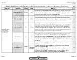
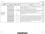
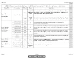
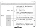
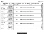
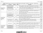
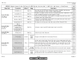
Menu Path
Parameter
Default
Range
Description
51.1
52.2
52.4
LEGEND -
Password Access:
(U)=User, (S)=Service, (O)=OEM, Shaded = Commonly Used, ** = Must Set, X = Has Function, / = Partial Function
LMV
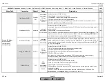
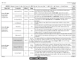
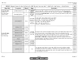
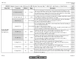
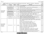
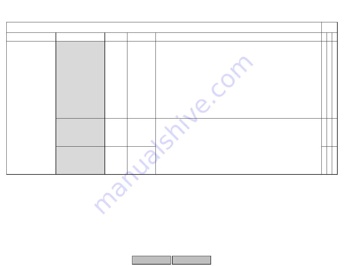
O2MaxManVariable (S)
35%
1-50%
x x
O2MinManVariable (S)
-35%
-50-0%
x x
x x
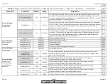
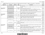
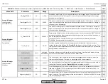
Influences the behavior of the O2 precontrol (see
LoadCtrlSuspend
). Setting is determined
by whether or not a change in air flow (air pressure in the burner head) impacts the fuel
flow. Three possibilites exist:
1) like theory - a change in air flow (pressure) does not impact fuel flow.
2) like P air - a change in air flow (pressure) does impact fuel flow.
3) LambdaFact1 - ignores the learned value and assumes a Lambda factor of 1. This setting is
not recommended for most burners. Both 'like theory' and 'like P air' use the Lambda factors
learned at each point during O2 control curve commissioning, which is preferred.
NOTE: 'like theory' is typical for oil, and 'like P air' is typical for gas.
NOTE: The burner behavior discussed above can only be observed if a fuel flow meter is used
during commissioning.
These settings limit the amount of positive or negative O2 trim that can take place by limiting
how much the manipulated variable can be changed. O2MaxManVariable limits how much
the air damper can trim open. O2MinManVariable limits how much the air damper can trim
closed. These limits must be set so that they are not reached during normal operation with
normal variances in ambient conditions. However, they also must be set so that when the
limits are reached, an unsafe condition does not occur with the burner. Reaching these
limits will cause a deactivation of the O2 trim or lockout depending upon how parameter
OptgMode
is set. See Section 6 for more detail.
Type Air Change (S)
like theory
like theory
like P air
LambdaFact1
Params & Display>
O2Contr/Alarm>
Gas/Oil Settings>
Control Param
SCC Inc.
Page 25
Section 3
HOME
HOME
P - LIST
Summary of Contents for LMV 5 Series
Page 2: ...Intentionally Left Blank ...
Page 41: ...LMV Series Technical Instructions Document No LV5 1000 SCC Inc Page 7 Section 2 HOME ...
Page 42: ...Technical Instructions LMV Series Document No LV5 1000 Section 2 Page 8 SCC Inc HOME ...
Page 43: ...LMV Series Technical Instructions Document No LV5 1000 SCC Inc Page 9 Section 2 HOME ...
Page 44: ...Technical Instructions LMV Series Document No LV5 1000 Section 2 Page 10 SCC Inc HOME ...
Page 45: ...LMV Series Technical Instructions Document No LV5 1000 SCC Inc Page 11 Section 2 HOME ...
Page 46: ...Technical Instructions LMV Series Document No LV5 1000 Section 2 Page 12 SCC Inc HOME ...
Page 47: ...LMV Series Technical Instructions Document No LV5 1000 SCC Inc Page 13 Section 2 HOME ...
Page 48: ...Technical Instructions LMV Series Document No LV5 1000 Section 2 Page 14 SCC Inc HOME ...
Page 49: ...LMV Series Technical Instructions Document No LV5 1000 SCC Inc Page 15 Section 2 HOME ...
Page 50: ...Technical Instructions LMV Series Document No LV5 1000 Section 2 Page 16 SCC Inc HOME ...
Page 51: ...LMV Series Technical Instructions Document No LV5 1000 SCC Inc Page 17 Section 2 HOME ...
Page 52: ...Technical Instructions LMV Series Document No LV5 1000 Section 2 Page 18 SCC Inc HOME ...
Page 53: ...LMV Series Technical Instructions Document No LV5 1000 SCC Inc Page 19 Section 2 HOME ...
Page 54: ...Technical Instructions LMV Series Document No LV5 1000 Section 2 Page 20 SCC Inc HOME ...
Page 55: ...LMV Series Technical Instructions Document No LV5 1000 SCC Inc Page 21 Section 2 HOME ...
Page 373: ...Intentionally Left Blank ...