


Technical
Instructions
LMV
Series
Document
No.
LV5
‐
1000
Section
5
Page
12
SCC
Inc.
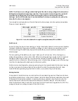
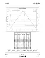
NOTE:
The
total
time
of
the
standardization
shown
in
Figure
5
‐
3
is
70
seconds
with
a
VFD
ramp
time
of
30
seconds.
Longer
VFD
/
LMV52
ramp
times
will
increase
the
total
time
taken
for
the
standardization.
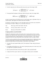
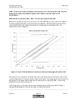
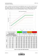
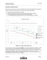
NOTE:
The
VFD
is
spanned
so
20mA
=
62Hz.
Thus,
19.5mA
is
approximately
60Hz.
Based
off
of
the
RPM
that
was
read
at
19.5
mA
(in
this
case
3544
RPM)
and
an
assumption
of
0
RPM
at
minimum
signal
(typically
4mA),
a
two
point
linear
interpolation
is
automatically
done
by
the
LMV52,
which
establishes
the
linear
relationship
between
the
analog
signal
and
the
blower
RPM
.
This
relationship
is
shown
in
Figure
5
‐
4.
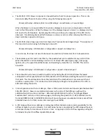
Figure
5
‐
4:
Result
of
Standardization
(2
‐
pole
blower
motor)
and
Analog
Signal
Correction
Limits
When
the
burner
is
in
operation,
the
LMV52
has
active,
closed
‐
loop
control
of
the
blower
motor
speed
and
can
compensate
for
motor
slip
and
other
factors
within
limits.
The
analog
signal
can
be
increased
to
compensate
for
low
blower
RPM
and
decreased
to
compensate
for
high
blower
RPM.
These
analog
signal
limits
are
also
shown
in
Figure
5
‐
4.
If
the
analog
signal
is
increased
to
the
maximum
allowable
signal
and
the
blower
RPM
is
still
low,
a
message
will
be
displayed
on
the
AZL
that
states
“Fan
speed
not
reached”.
HOME
Summary of Contents for LMV 5 Series
Page 2: ...Intentionally Left Blank ...
Page 41: ...LMV Series Technical Instructions Document No LV5 1000 SCC Inc Page 7 Section 2 HOME ...
Page 42: ...Technical Instructions LMV Series Document No LV5 1000 Section 2 Page 8 SCC Inc HOME ...
Page 43: ...LMV Series Technical Instructions Document No LV5 1000 SCC Inc Page 9 Section 2 HOME ...
Page 44: ...Technical Instructions LMV Series Document No LV5 1000 Section 2 Page 10 SCC Inc HOME ...
Page 45: ...LMV Series Technical Instructions Document No LV5 1000 SCC Inc Page 11 Section 2 HOME ...
Page 46: ...Technical Instructions LMV Series Document No LV5 1000 Section 2 Page 12 SCC Inc HOME ...
Page 47: ...LMV Series Technical Instructions Document No LV5 1000 SCC Inc Page 13 Section 2 HOME ...
Page 48: ...Technical Instructions LMV Series Document No LV5 1000 Section 2 Page 14 SCC Inc HOME ...
Page 49: ...LMV Series Technical Instructions Document No LV5 1000 SCC Inc Page 15 Section 2 HOME ...
Page 50: ...Technical Instructions LMV Series Document No LV5 1000 Section 2 Page 16 SCC Inc HOME ...
Page 51: ...LMV Series Technical Instructions Document No LV5 1000 SCC Inc Page 17 Section 2 HOME ...
Page 52: ...Technical Instructions LMV Series Document No LV5 1000 Section 2 Page 18 SCC Inc HOME ...
Page 53: ...LMV Series Technical Instructions Document No LV5 1000 SCC Inc Page 19 Section 2 HOME ...
Page 54: ...Technical Instructions LMV Series Document No LV5 1000 Section 2 Page 20 SCC Inc HOME ...
Page 55: ...LMV Series Technical Instructions Document No LV5 1000 SCC Inc Page 21 Section 2 HOME ...
Page 373: ...Intentionally Left Blank ...