

Technical
Instructions
LMV
Series
Document
No.
LV5
‐
1000
Section
6
Page
22
SCC
Inc.
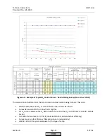
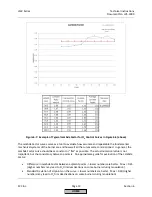
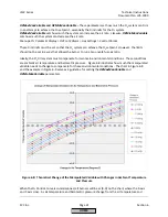
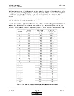
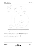
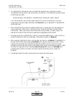
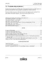
barometric
pressure
that
existed
during
O
2
Control
Curve
commissioning,
the
manipulated
variable
must
change
to
keep
the
same
%O
2
in
the
stack.
An
example
is
done
below
and
illustrated
in
Figure
6
‐
9:
Air
temperature
during
O
2
Control
Curve
commissioning
=
80°F
Barometric
pressure
during
O
2
Control
Curve
commissioning
=
30.0
inHg
Maximum
expected
air
temperature
=
120°F
(+40°F
compared
to
commissioning)
Minimum
expected
air
temperature
=
30°F
(
‐
50°F
compared
to
commissioning)
Maximum
expected
barometric
pressure
=
31.5
inHg
(+1.5
inHg
compared
to
commissioning)
Minimum
expected
barometric
pressure
=
28.0
inHg
(
‐
2.0
inHg
compared
to
commissioning)
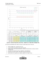
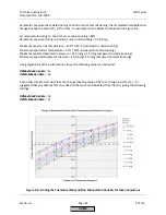
Using
Figure
6
‐
8
and
the
information
above,
the
following
values
can
be
found:
O2MaxManVariable
=
13
O2MinManVariable
=
‐
16
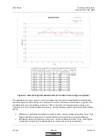
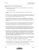
Since
other
small
factors
exist
that
can
change
(heating
value
of
the
fuel,
change
in
draft,
etc.),
it
is
suggested
that
an
additional
5%
are
added
to
the
max
and
subtracted
from
the
min,
giving
the
following
settings:
O2MaxManVariable
=
18
O2MinManVariable
=
‐
21
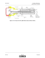
Figure
6
‐
9:
Finding
the
Theoretical
Max
and
Min
Manipulated
Variable
for
Given
Conditions
HOME
Summary of Contents for LMV 5 Series
Page 2: ...Intentionally Left Blank ...
Page 41: ...LMV Series Technical Instructions Document No LV5 1000 SCC Inc Page 7 Section 2 HOME ...
Page 42: ...Technical Instructions LMV Series Document No LV5 1000 Section 2 Page 8 SCC Inc HOME ...
Page 43: ...LMV Series Technical Instructions Document No LV5 1000 SCC Inc Page 9 Section 2 HOME ...
Page 44: ...Technical Instructions LMV Series Document No LV5 1000 Section 2 Page 10 SCC Inc HOME ...
Page 45: ...LMV Series Technical Instructions Document No LV5 1000 SCC Inc Page 11 Section 2 HOME ...
Page 46: ...Technical Instructions LMV Series Document No LV5 1000 Section 2 Page 12 SCC Inc HOME ...
Page 47: ...LMV Series Technical Instructions Document No LV5 1000 SCC Inc Page 13 Section 2 HOME ...
Page 48: ...Technical Instructions LMV Series Document No LV5 1000 Section 2 Page 14 SCC Inc HOME ...
Page 49: ...LMV Series Technical Instructions Document No LV5 1000 SCC Inc Page 15 Section 2 HOME ...
Page 50: ...Technical Instructions LMV Series Document No LV5 1000 Section 2 Page 16 SCC Inc HOME ...
Page 51: ...LMV Series Technical Instructions Document No LV5 1000 SCC Inc Page 17 Section 2 HOME ...
Page 52: ...Technical Instructions LMV Series Document No LV5 1000 Section 2 Page 18 SCC Inc HOME ...
Page 53: ...LMV Series Technical Instructions Document No LV5 1000 SCC Inc Page 19 Section 2 HOME ...
Page 54: ...Technical Instructions LMV Series Document No LV5 1000 Section 2 Page 20 SCC Inc HOME ...
Page 55: ...LMV Series Technical Instructions Document No LV5 1000 SCC Inc Page 21 Section 2 HOME ...
Page 373: ...Intentionally Left Blank ...