


LMV Series
Technical Instructions
Document No. LV5-1000
SCC Inc.
Page 3
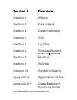
Section 1
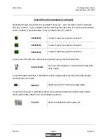
Control Panel Components (continued)
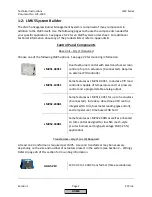
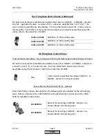
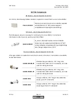
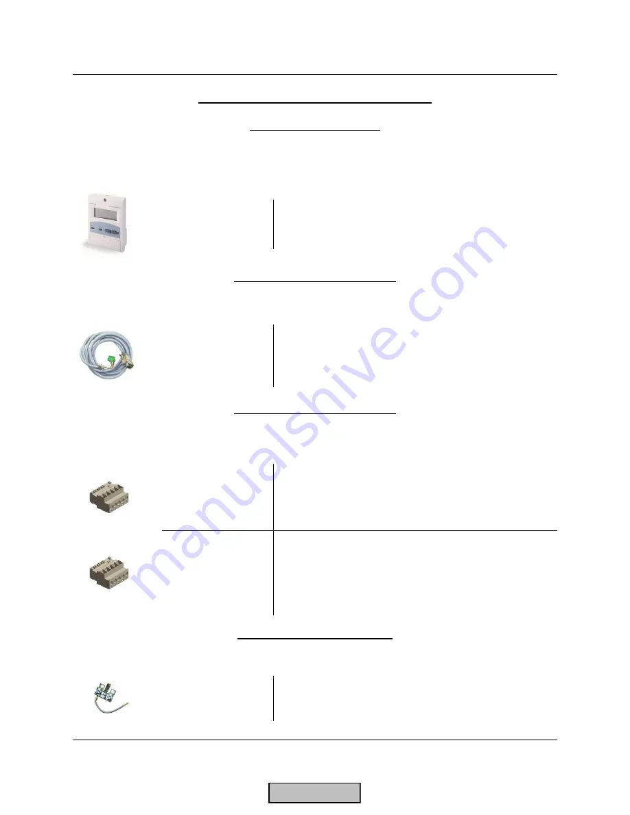
Display – Qty (1) Required
Each LMV5 must be equipped with one AZL52.40B1 display. See page 25 for mounting
information and panel cutout dimensions.
AZL52.40B1
Display with Modbus port, PC port, backlight, six
languages available
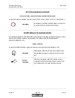
Display Cable – Qty (1) Required
Each LMV5 must be equipped with a cable to connect the AZL52 display to the LMV5.
AGG5.635
Pre-made 9 foot cable for connecting the AZL52
display to the LMV5
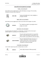
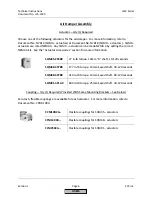
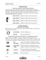
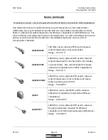
Base Plug Set – Qty (1) Required
The terminal plug sets for the LMV5 are sold separately. Each LMV5 needs one base plug set.
Additional plug sets are available (see “Control Panel Spare Parts”).
AGG5.720
Plug set containing all terminals for a typical LMV5
system. Will accommodate a system with O
2
trim,
three actuators, one transformer, and no fuel meters
AGG5.7COMPLETE
Plug set containing all terminals necessary for a
maximum LMV5 system. Will accommodate a
system with a VFD, O
2
trim, six actuators, two
transformers, and two fuel meters
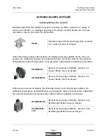
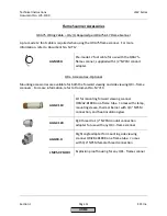
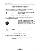
Strain Relief – Qty (1) Required
A strain relief is required to ground the CANbus shield to the LMV5.
AGG5.110
Strain relief and actuator CANbus grounding
HOME
Summary of Contents for LMV 5 Series
Page 2: ...Intentionally Left Blank ...
Page 41: ...LMV Series Technical Instructions Document No LV5 1000 SCC Inc Page 7 Section 2 HOME ...
Page 42: ...Technical Instructions LMV Series Document No LV5 1000 Section 2 Page 8 SCC Inc HOME ...
Page 43: ...LMV Series Technical Instructions Document No LV5 1000 SCC Inc Page 9 Section 2 HOME ...
Page 44: ...Technical Instructions LMV Series Document No LV5 1000 Section 2 Page 10 SCC Inc HOME ...
Page 45: ...LMV Series Technical Instructions Document No LV5 1000 SCC Inc Page 11 Section 2 HOME ...
Page 46: ...Technical Instructions LMV Series Document No LV5 1000 Section 2 Page 12 SCC Inc HOME ...
Page 47: ...LMV Series Technical Instructions Document No LV5 1000 SCC Inc Page 13 Section 2 HOME ...
Page 48: ...Technical Instructions LMV Series Document No LV5 1000 Section 2 Page 14 SCC Inc HOME ...
Page 49: ...LMV Series Technical Instructions Document No LV5 1000 SCC Inc Page 15 Section 2 HOME ...
Page 50: ...Technical Instructions LMV Series Document No LV5 1000 Section 2 Page 16 SCC Inc HOME ...
Page 51: ...LMV Series Technical Instructions Document No LV5 1000 SCC Inc Page 17 Section 2 HOME ...
Page 52: ...Technical Instructions LMV Series Document No LV5 1000 Section 2 Page 18 SCC Inc HOME ...
Page 53: ...LMV Series Technical Instructions Document No LV5 1000 SCC Inc Page 19 Section 2 HOME ...
Page 54: ...Technical Instructions LMV Series Document No LV5 1000 Section 2 Page 20 SCC Inc HOME ...
Page 55: ...LMV Series Technical Instructions Document No LV5 1000 SCC Inc Page 21 Section 2 HOME ...
Page 373: ...Intentionally Left Blank ...