


LMV Series
Technical Instructions
LV5-1000
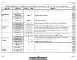
Menu Path
Parameter
Default
Range
Description
51.1
52.2
52.4
LEGEND -
Password Access:
(U)=User, (S)=Service, (O)=OEM, Shaded = Commonly Used, ** = Must Set, X = Has Function, / = Partial Function
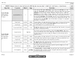
LMV
Params & Display>
O2Contr/Alarm>
Gas/Oil Settings>
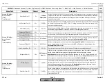
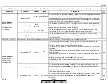
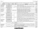
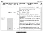
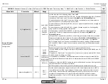
O2 Alarm
NumMinUntilDeact (S)
1
1-5
If the measured %O2 exceeds
O2 MaxValue
or goes lower than the
O2 Alarm
for a time
longer than
Time O2 Alarm
(O2 exceedances), then the O2 trim will deactivate. If parameter
OptgMode
is set to 'O2 Control' during an exceedance, a lockout will occur. If parameter
OptgMode
is set to 'ConAutoDeac' during an exceedance, then the O2 trim will temporarily
deactivate (burner keeps running on position control curves). If the measured %O2 comes
back between
O2 MaxValue
and the
O2 Alarm
, then the O2 trim will attempt to reactivate.
This parameter determines how many times the O2 trim can deactivate and reactivate. This
parameter is valid only if
OptgMode
is set to 'ConAutoDeac'. A setting of 1 = no repetitions,
a setting of 5 = 4 repetitions.
x x
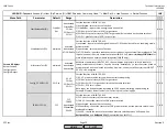
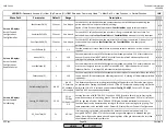
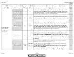
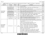
Calc PI again (O)
deact
activated
deactivated
If
Tau High-FireOEM
or
Tau Low-FireOEM
are manually adjusted, then the PI values need to
be recalculated based on the new Tau values. Setting this parameter to activated will
recalculate the high and low fire PI values.
x x
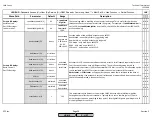
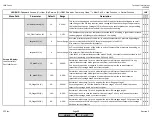
Proportional band and integral component for O2 trim response. Automatically set based on
the Tau (delay time) measured at the
LowfireAdaptPtNo
. Both the P and the I can be
manually adjusted, but this is typically not necessary.
This is the delay time that is automatically measured at
LowfireAdaptPtNo
. Delay time is
the amount of time that a fuel air ratio change at the burner takes to reach the O2 sensor in
the stack. The delay time is shorter at high fire and longer at low fire due to gas velocity
through the boiler.
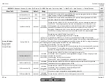
x x
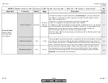
Tau Low-Fire
(delay time at low fire) can be manually adjusted here if necessary, but manual
adjustment is typically not necessary.
x x
x x
x x
Read Only
Not Set
I Low-Fire (S)
Tau Low-Fire OEM (O)
Tau Low-Fire (U)
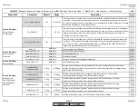
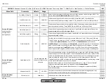
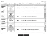
P High-Fire (S)
Params & Display>
O2Contr/Alarm>
Gas/Oil Settings>
Control Param>
PI
P Low-Fire (S)
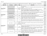
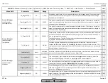
Tau High-Fire (U)
0-500s
Not Set
1-60s
Not Set
3-500%
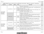
x x
x x
x x
x x
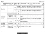
Tau High-Fire
(delay time at high fire) can be manually adjusted here if necessary, but
manual adjustment is typically not necessary.
This is the delay time that is automatically measured at high fire (the highest point in the
curve). See
Tau Low-Fire
for explanation.
Proportional band and integral component for O2 trim response. Automatically set based on
the Tau (delay time) measured at high fire (the highest point in the curve). Both the P and
the I can be manually adjusted, but this is typically not necessary.
Not Set
3-500%
Not Set
0-500s
Not Set
1-60s
I High-Fire (S)
Tau High-FireOEM (O)
Read Only
SCC Inc.
Page 23
Section 3
HOME
HOME
P - LIST
Summary of Contents for LMV 5 Series
Page 2: ...Intentionally Left Blank ...
Page 41: ...LMV Series Technical Instructions Document No LV5 1000 SCC Inc Page 7 Section 2 HOME ...
Page 42: ...Technical Instructions LMV Series Document No LV5 1000 Section 2 Page 8 SCC Inc HOME ...
Page 43: ...LMV Series Technical Instructions Document No LV5 1000 SCC Inc Page 9 Section 2 HOME ...
Page 44: ...Technical Instructions LMV Series Document No LV5 1000 Section 2 Page 10 SCC Inc HOME ...
Page 45: ...LMV Series Technical Instructions Document No LV5 1000 SCC Inc Page 11 Section 2 HOME ...
Page 46: ...Technical Instructions LMV Series Document No LV5 1000 Section 2 Page 12 SCC Inc HOME ...
Page 47: ...LMV Series Technical Instructions Document No LV5 1000 SCC Inc Page 13 Section 2 HOME ...
Page 48: ...Technical Instructions LMV Series Document No LV5 1000 Section 2 Page 14 SCC Inc HOME ...
Page 49: ...LMV Series Technical Instructions Document No LV5 1000 SCC Inc Page 15 Section 2 HOME ...
Page 50: ...Technical Instructions LMV Series Document No LV5 1000 Section 2 Page 16 SCC Inc HOME ...
Page 51: ...LMV Series Technical Instructions Document No LV5 1000 SCC Inc Page 17 Section 2 HOME ...
Page 52: ...Technical Instructions LMV Series Document No LV5 1000 Section 2 Page 18 SCC Inc HOME ...
Page 53: ...LMV Series Technical Instructions Document No LV5 1000 SCC Inc Page 19 Section 2 HOME ...
Page 54: ...Technical Instructions LMV Series Document No LV5 1000 Section 2 Page 20 SCC Inc HOME ...
Page 55: ...LMV Series Technical Instructions Document No LV5 1000 SCC Inc Page 21 Section 2 HOME ...
Page 373: ...Intentionally Left Blank ...