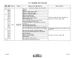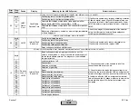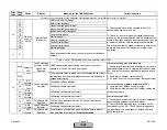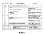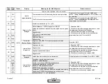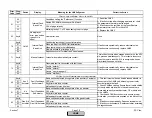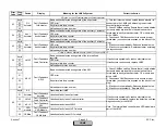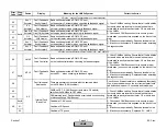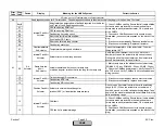
Error
Code
Diag.
Code
Device
Display
Meaning for the LMV5x System
Corrective Action
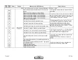
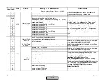
1A
01
Slope too steep A section of actuator curve is too steep.
Check maximum slope sections of actuator curves.
Maximum allowable slopes are as follows:
- 3.6° per 0.1% load (30 sec ramp)
- 1.8° per 0.1% load (60 sec ramp)
- 0.9° per 0.1% load (120 sec ramp)
If these maximums are exceeded, adjust curve section
below these maximum slopes.
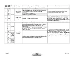
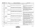
1B
Any #
Operation in
Parameter
Setting Mode quit
Curve parameters (actuator curves) programming mode is still
active in phase 62 (drive to low fire and shutdown) and the
target positions (normal operation) have not been reached.
When setting the curve parameters, the plant should be
operated in manual mode. This prevents the internal
load controller from triggering the change to shutdown.
Response of the internal temperature limiter can trigger
this same fault. However, the curve point currently
being set can still be stored in standby or lockout.
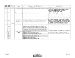
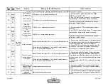
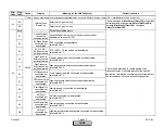
Any #
Ignition positions for activated actuators (or VSD) have not
been set. See diagnostic code to indicate the faulted actuator.
01..3F
The diagnostic value is made up of the following faults or their
combinations (the individual diagnostic codes are added up in
hexadecimal format).
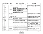
01
Ignition position for air actuator not set.
02
Ignition position for active fuel actuator not set.
04
Ignition position for aux1 actuator not set.
08
Ignition position for aux2 actuator not set.
10
Ignition position for VSD not set.
20
Ignition position for aux3 actuator not set.
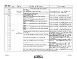
Fault with Actuator (VSD) Positioning or Actuator (VSD) Run Time
Set the ignition position of the actuator(s). The ignition
positions for each fuel are independent, and the
positions are also independent of the low fire position.
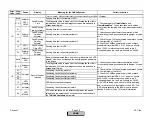
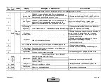
1C
LMV5
Ignition Pos not
defined
Section 7
Page 28
SCC Inc.
HOME
HOME
Summary of Contents for LMV 5 Series
Page 2: ...Intentionally Left Blank ...
Page 41: ...LMV Series Technical Instructions Document No LV5 1000 SCC Inc Page 7 Section 2 HOME ...
Page 42: ...Technical Instructions LMV Series Document No LV5 1000 Section 2 Page 8 SCC Inc HOME ...
Page 43: ...LMV Series Technical Instructions Document No LV5 1000 SCC Inc Page 9 Section 2 HOME ...
Page 44: ...Technical Instructions LMV Series Document No LV5 1000 Section 2 Page 10 SCC Inc HOME ...
Page 45: ...LMV Series Technical Instructions Document No LV5 1000 SCC Inc Page 11 Section 2 HOME ...
Page 46: ...Technical Instructions LMV Series Document No LV5 1000 Section 2 Page 12 SCC Inc HOME ...
Page 47: ...LMV Series Technical Instructions Document No LV5 1000 SCC Inc Page 13 Section 2 HOME ...
Page 48: ...Technical Instructions LMV Series Document No LV5 1000 Section 2 Page 14 SCC Inc HOME ...
Page 49: ...LMV Series Technical Instructions Document No LV5 1000 SCC Inc Page 15 Section 2 HOME ...
Page 50: ...Technical Instructions LMV Series Document No LV5 1000 Section 2 Page 16 SCC Inc HOME ...
Page 51: ...LMV Series Technical Instructions Document No LV5 1000 SCC Inc Page 17 Section 2 HOME ...
Page 52: ...Technical Instructions LMV Series Document No LV5 1000 Section 2 Page 18 SCC Inc HOME ...
Page 53: ...LMV Series Technical Instructions Document No LV5 1000 SCC Inc Page 19 Section 2 HOME ...
Page 54: ...Technical Instructions LMV Series Document No LV5 1000 Section 2 Page 20 SCC Inc HOME ...
Page 55: ...LMV Series Technical Instructions Document No LV5 1000 SCC Inc Page 21 Section 2 HOME ...
Page 373: ...Intentionally Left Blank ...

