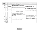


Error
Code
Diag.
Code
Device
Display
Meaning for the LMV5x System
Corrective Action
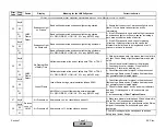
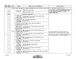
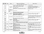
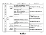
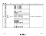
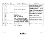
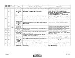
90
Aux 3
Actuator
Fault Feedback
Aux Actuator 3
Basic unit has detected a ROM-CRC error
on the auxiliary 3 actuator when checking its feedback signal
91
Air
Actuator
Fault Feedback
Air Actuator
Basic unit has detected a ROM-CRC error
on the air actuator when checking its feedback signal
92
Gas (Oil)
Actuator
Fault Feedback
Gas (Oil) Actuator
Basic unit has detected a ROM-CRC error
on the gas actuator when checking its feedback signal
93
Oil
Actuator
Fault Feedback
Oil Actuator
Basic unit has detected a ROM-CRC error
on the oil actuator when checking its feedback signal
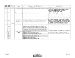
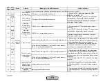
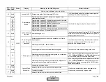
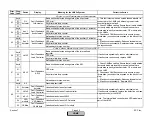
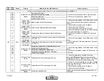
94
Aux 1
Actuator
Fault Feedback
Aux Actuator 1
Basic unit has detected a ROM-CRC error
on the auxiliary 1 actuator when checking its feedback signal
95
Aux 2
Actuator
Fault Feedback
Aux Actuator 2
Basic unit has detected a ROM-CRC error
on the auxiliary 2 actuator when checking its feedback signal
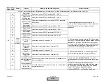
96
LMV5
Fault Feedback
Load Controller
Basic unit has detected a ROM-CRC error
on the load controller when checking its feedback signal
97
AZL5
Fault Feedback
AZL
Basic unit has detected a ROM-CRC error
on the AZLI when checking its feedback signal
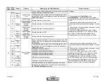
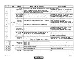
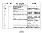
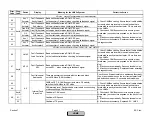
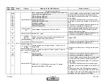
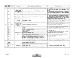
98
Fault two equal
Addresses
There are several components with the same address
on the CAN bus (CAN overflow)
Check to see if two actuators are addressed identically.
If so, erase the address on the incorrect actuator (hold
red button down about 10 seconds) and re-address.
99
CANBus OFF. A CANBus user (actuators, O2 module)
switches the CANBus to OFF mode.
9A
CAN warning level. Fault probably occurred when connecting
or disconnecting a CANBus user
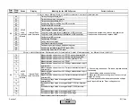
Any #
Overflow of CAN queue
01
Overflow of RX queue
02
Overflow of TX queue
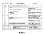
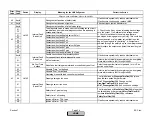
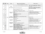
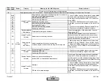
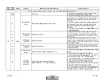
Fault with Base Unit (LMV5), or AZL5
9B
Internal Fault
Basic Unit
1) Check CANBus cabling. Ensure that all cable shields
(screens) which are located in the cable sheath are
terminated correctly at each actuator, O2 module, and
at the LMV5x...
2) Check each CANBus connector to ensure proper
termination (no conductors exposed on the back of the
plug)
3) If fault occurs sporadically: Reduce electrical noise.
4) If fault occurs constantly: Replace AZL.., LMV5
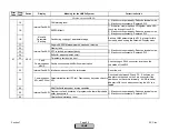
Fault with Connected actuators
1) Check CANBus cabling. Ensure that all cable shields
(screens) which are located in the cable sheath are
terminated correctly at each actuator, O2 module, and
at the LMV5x...
2) Check each CANBus connector to ensure proper
termination (no conductors exposed on the back of the
plug)
3) If fault occurs sporadically: Reduce electrical noise.
4) If fault occurs constantly: Replace actuator according
to diagnostic code.
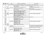
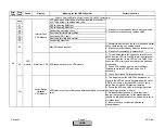
Any #
1) Check CANBus cabling. Ensure that all cable shields
(screens) which are located in the cable sheath are
terminated correctly at each actuator, O2 module, and
at the LMV5x...
2) Check each CANBus connector to ensure proper
termination (no conductors exposed on the back of the
plug)
3) If fault occurs sporadically: Reduce electrical noise.
4) If fault occurs constantly: Replace actuator according
to diagnostic code.
Any #
All
Section 7
Page 41
SCC Inc.
HOME
HOME
Summary of Contents for LMV 5 Series
Page 2: ...Intentionally Left Blank ...
Page 41: ...LMV Series Technical Instructions Document No LV5 1000 SCC Inc Page 7 Section 2 HOME ...
Page 42: ...Technical Instructions LMV Series Document No LV5 1000 Section 2 Page 8 SCC Inc HOME ...
Page 43: ...LMV Series Technical Instructions Document No LV5 1000 SCC Inc Page 9 Section 2 HOME ...
Page 44: ...Technical Instructions LMV Series Document No LV5 1000 Section 2 Page 10 SCC Inc HOME ...
Page 45: ...LMV Series Technical Instructions Document No LV5 1000 SCC Inc Page 11 Section 2 HOME ...
Page 46: ...Technical Instructions LMV Series Document No LV5 1000 Section 2 Page 12 SCC Inc HOME ...
Page 47: ...LMV Series Technical Instructions Document No LV5 1000 SCC Inc Page 13 Section 2 HOME ...
Page 48: ...Technical Instructions LMV Series Document No LV5 1000 Section 2 Page 14 SCC Inc HOME ...
Page 49: ...LMV Series Technical Instructions Document No LV5 1000 SCC Inc Page 15 Section 2 HOME ...
Page 50: ...Technical Instructions LMV Series Document No LV5 1000 Section 2 Page 16 SCC Inc HOME ...
Page 51: ...LMV Series Technical Instructions Document No LV5 1000 SCC Inc Page 17 Section 2 HOME ...
Page 52: ...Technical Instructions LMV Series Document No LV5 1000 Section 2 Page 18 SCC Inc HOME ...
Page 53: ...LMV Series Technical Instructions Document No LV5 1000 SCC Inc Page 19 Section 2 HOME ...
Page 54: ...Technical Instructions LMV Series Document No LV5 1000 Section 2 Page 20 SCC Inc HOME ...
Page 55: ...LMV Series Technical Instructions Document No LV5 1000 SCC Inc Page 21 Section 2 HOME ...
Page 373: ...Intentionally Left Blank ...