


LMV
Series
Technical
Instructions
Document
No.
LV5
‐
1000
SCC
Inc.
Page
25
Section
4
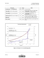
1.
If
possible,
shut
off
the
burner
switch.
Let
the
burner
get
back
to
Phase
12
(standby).
2.
Access
the
cold
start
parameters
through
the
following
menu
path:
Params
&
Display
>
LoadController
>
ColdStart
Set
parameter
ThresholdOn
to
the
minimum
permissible
temperature
where
the
burner
can
be
released
to
modulate.
Below
this
temperature,
cold
start
will
engage
on
initial
startup
(not
during
normal
operation).
Set
ThresholdOff
to
a
temperature
higher
than
ThresholdOn
.
If
already
engaged,
cold
start
will
disengage
at
the
ThresholdOff
temperature.
Setting
ThresholdOn
and
ThresholdOff
is
required
for
cold
start.
NOTE:
Parameters
ThresholdOn
and
ThresholdOff
are
percentages
based
on
the
current
setpoint
(W1).
If
an
additional
temperature
sensor
is
used
on
a
steam
boiler,
ThresholdOn
and
ThresholdOff
will
be
based
on
parameter
Setp
AddSensor.
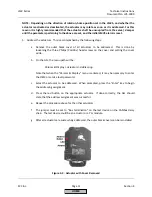
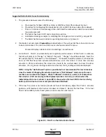
3.
For
a
steam
boiler
that
is
on
a
common
header
with
other
steam
boilers,
an
additional
temperature
sensor
is
required
for
cold
start.
This
will
typically
be
a
Pt1000
or
Ni1000
RTD
wired
to
terminal
X60.
Pt100
is
possible
but
not
recommended.
Choose
the
appropriate
sensor
via
parameter
AdditionalSens
.
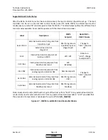
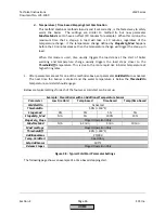
4.
There
are
four
basic
ways
that
the
cold
start
can
be
set.
These
are:
a.
Basic
Low
Fire
Hold
The
LMV5
will
be
held
at
low
fire
until
the
ThresholdOff
temperature
is
reached,
and
then
the
LMV5
will
be
released
to
modulate.
This
“hold”
will
re
‐
engage
when
the
temperature
falls
below
the
ThresholdOn
value.
Parameter
StageLoad
must
be
set
to
0.
b.
Temperature
‐
based
Stepping
Start
The
LMV5
will
be
held
at
low
fire
until
a
certain
temperature
change
is
detected,
and
then
a
step
up
in
burner
output
(load)
will
be
taken.
This
continues
until
the
ThresholdOff
temperature
is
reached.
This
will
achieve
the
ThresholdOff
temperature
faster
than
a
basic
low
fire
hold.
Parameter
StageLoad
must
be
set
to
a
value
greater
than
0,
since
the
step
‐
up
in
load
is
determined
by
this
parameter.
Parameter
StageSetp_Mod
must
also
be
set
to
determine
the
amount
of
temperature
change
that
will
trigger
a
step
‐
up
in
load.
Parameter
MaxTmeMod
should
be
set
to
a
high
number
(30
min)
so
that
it
has
no
effect.
c.
Time
‐
based
Stepping
Start
The
LMV5
will
be
held
at
low
fire
until
a
certain
time
elapses,
and
then
a
step
‐
up
in
load
will
be
taken.
This
continues
until
the
ThresholdOff
value
is
reached.
StageLoad
must
be
set
to
a
value
greater
than
0,
since
the
step
‐
up
in
load
is
determined
by
this
parameter.
Parameter
StageSetp_Mod
should
be
set
to
a
high
number
(80%)
so
that
it
has
no
effect.
Parameter
MaxTmeMod
is
set
to
determine
how
much
time
should
elapse
before
the
next
load
step
is
triggered.
HOME
Summary of Contents for LMV 5 Series
Page 2: ...Intentionally Left Blank ...
Page 41: ...LMV Series Technical Instructions Document No LV5 1000 SCC Inc Page 7 Section 2 HOME ...
Page 42: ...Technical Instructions LMV Series Document No LV5 1000 Section 2 Page 8 SCC Inc HOME ...
Page 43: ...LMV Series Technical Instructions Document No LV5 1000 SCC Inc Page 9 Section 2 HOME ...
Page 44: ...Technical Instructions LMV Series Document No LV5 1000 Section 2 Page 10 SCC Inc HOME ...
Page 45: ...LMV Series Technical Instructions Document No LV5 1000 SCC Inc Page 11 Section 2 HOME ...
Page 46: ...Technical Instructions LMV Series Document No LV5 1000 Section 2 Page 12 SCC Inc HOME ...
Page 47: ...LMV Series Technical Instructions Document No LV5 1000 SCC Inc Page 13 Section 2 HOME ...
Page 48: ...Technical Instructions LMV Series Document No LV5 1000 Section 2 Page 14 SCC Inc HOME ...
Page 49: ...LMV Series Technical Instructions Document No LV5 1000 SCC Inc Page 15 Section 2 HOME ...
Page 50: ...Technical Instructions LMV Series Document No LV5 1000 Section 2 Page 16 SCC Inc HOME ...
Page 51: ...LMV Series Technical Instructions Document No LV5 1000 SCC Inc Page 17 Section 2 HOME ...
Page 52: ...Technical Instructions LMV Series Document No LV5 1000 Section 2 Page 18 SCC Inc HOME ...
Page 53: ...LMV Series Technical Instructions Document No LV5 1000 SCC Inc Page 19 Section 2 HOME ...
Page 54: ...Technical Instructions LMV Series Document No LV5 1000 Section 2 Page 20 SCC Inc HOME ...
Page 55: ...LMV Series Technical Instructions Document No LV5 1000 SCC Inc Page 21 Section 2 HOME ...
Page 373: ...Intentionally Left Blank ...