


LMV
Series
Technical
Instructions
Document
No.
LV5
‐
1000
SCC
Inc.
Page
7
Section
6
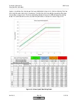
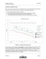
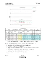
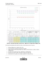
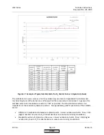
The
O
2
Ratio
Control
Curve
reflects
the
%O
2
that
resulted
from
setting
the
Fuel
‐
Air
Ratio
Control
Curve.
The
O
2
Control
Curve
is
the
target
for
the
O
2
trim
system
when
it
is
activated.
When
the
burner
is
transitioned
from
the
O
2
Ratio
Control
Curve
to
the
O
2
Control
Curve
by
increasing
the
Standardized
Value,
the
Lambda
Factor
will
be
learned
and
recorded
at
that
specific
point.
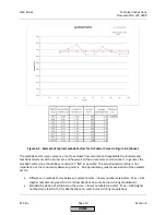
A
larger
gap
between
the
O
2
Ratio
Control
Curve
and
the
O
2
Control
Curve
will
give
the
LMV52
the
best
opportunity
to
learn
the
Lambda
Factor
of
the
burner,
and
thus
yield
the
best
pre
‐
control
when
the
burner
is
modulating.
A
gap
of
1%
O
2
or
more
is
ideal,
and
it
is
typically
achievable
on
nozzle
mixing
burners
with
no
or
low
percentages
of
FGR.
A
1%
gap
is
typically
not
achievable
on
premix
mesh
burners
or
on
nozzle
mixing
burners
that
use
a
high
percentage
of
FGR.
This
gap
also
sets
the
available
quantity
of
"lean"
trim
for
an
LMV52.240,
and
that
is
why
the
minimum
recommended
gap
for
an
LMV52.240
is
1%.
The
LMV52.440
uses
a
different
O
2
trim
algorithm
for
premix,
mesh
and
high
percentage
FGR
burners
and
can
deal
with
a
minimum
gap
of
0.5%.
O
2
Trim
Configuration
(Parameterization)
Before
Commissioning
The
procedure
below
assumes
an
LMV52
with
default
parameters
for
the
O2
Contr/Alarm
menu
and
the
O2
Module
menu.
If
the
LMV52
is
mounted
to
a
burner
/
boiler,
the
burner
/
boiler
OEM
may
have
already
changed
the
parameters
from
the
default
setting
and
parameterized
the
LMV52
for
the
application.
This
procedure
also
assumes
that
all
O
2
trim
components
are
installed
and
wired
correctly,
and
that
the
O
2
trim
will
be
commissioned
on
natural
gas.
Section
3
gives
a
detailed
explanation
of
all
of
the
parameters
in
the
LMV52
as
well
as
highlights
which
parameters
must
be
set
(marked
with
a
double
asterisk
**)
and
which
parameters
are
frequently
used
(shaded).
This
procedure
gives
a
general
guideline
of
what
parameters
need
to
be
set
on
both
a
traditional
nozzle
mixing
burner
with
little
to
no
FGR,
and
also
for
low
and
ultra
‐
low
NOx
burners
that
are
pre
‐
mix
mesh
type
or
high
percentage
FGR.
Every
burner
is
different,
so
it
is
likely
that
every
burner
will
need
a
somewhat
unique
parameter
set
to
run
correctly.
1.
Log
in
at
the
OEM
password
level.
From
the
factory,
the
OEM
password
for
the
LMV5
is
"START".
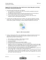
2.
If
not
done
so
already,
activate
the
O
2
sensor
using
the
following
menu
path:
Params
&
Display
>
O2
Module
>
Configuration
>
O2
Sensor
=
QGO20
3.
If
being
used,
configure
the
appropriate
temperature
sensors
for
blower
inlet
air
temperature
and
stack
temperature.
This
is
done
through
the
following
menu
path:
Params
&
Display
>
O2
Module
>
Configuration
>
SupAirTempSens
Params
&
Display
>
O2
Module
>
Configuration
>
FlueGasTempSens
Parameter
SupAirTempSens
activates
and
configures
the
blower
inlet
air
temperature
sensor.
Parameter
FlueGasTempSens
activates
and
configures
the
stack
temperature
sensor.
Options
are
Ni1000
or
Pt1000
2
‐
wire
sensors
for
both
inputs.
HOME
Summary of Contents for LMV 5 Series
Page 2: ...Intentionally Left Blank ...
Page 41: ...LMV Series Technical Instructions Document No LV5 1000 SCC Inc Page 7 Section 2 HOME ...
Page 42: ...Technical Instructions LMV Series Document No LV5 1000 Section 2 Page 8 SCC Inc HOME ...
Page 43: ...LMV Series Technical Instructions Document No LV5 1000 SCC Inc Page 9 Section 2 HOME ...
Page 44: ...Technical Instructions LMV Series Document No LV5 1000 Section 2 Page 10 SCC Inc HOME ...
Page 45: ...LMV Series Technical Instructions Document No LV5 1000 SCC Inc Page 11 Section 2 HOME ...
Page 46: ...Technical Instructions LMV Series Document No LV5 1000 Section 2 Page 12 SCC Inc HOME ...
Page 47: ...LMV Series Technical Instructions Document No LV5 1000 SCC Inc Page 13 Section 2 HOME ...
Page 48: ...Technical Instructions LMV Series Document No LV5 1000 Section 2 Page 14 SCC Inc HOME ...
Page 49: ...LMV Series Technical Instructions Document No LV5 1000 SCC Inc Page 15 Section 2 HOME ...
Page 50: ...Technical Instructions LMV Series Document No LV5 1000 Section 2 Page 16 SCC Inc HOME ...
Page 51: ...LMV Series Technical Instructions Document No LV5 1000 SCC Inc Page 17 Section 2 HOME ...
Page 52: ...Technical Instructions LMV Series Document No LV5 1000 Section 2 Page 18 SCC Inc HOME ...
Page 53: ...LMV Series Technical Instructions Document No LV5 1000 SCC Inc Page 19 Section 2 HOME ...
Page 54: ...Technical Instructions LMV Series Document No LV5 1000 Section 2 Page 20 SCC Inc HOME ...
Page 55: ...LMV Series Technical Instructions Document No LV5 1000 SCC Inc Page 21 Section 2 HOME ...
Page 373: ...Intentionally Left Blank ...