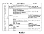
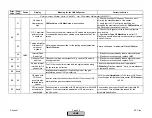
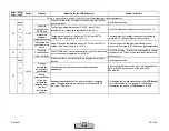

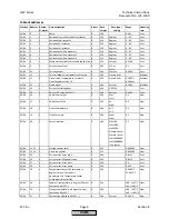
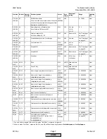
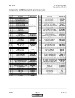
Error
Code
Diag.
Code
Device
Display
Meaning for the LMV5x System
Corrective Action
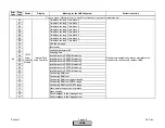
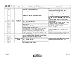
F0
Any #
Internal Fault
Basic Unit
Plausibility fault during calculation of interpolation values
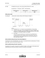
1) If fault occurs sporadically: Reduce electrical noise.
2) If fault occurs constantly: Replace LMV5.
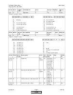
Any #
Internal fault during calculation of precontrol
01
-
02
-
03
-
04
-
05
-
06
Internal fault calculation of precontrol. Undefined value in the
curves used for the calculation
07
Internal fault calculation of precontrol. Undefined value for a
type of fuel parameter
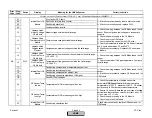
Any #
Code for faulty temperature values from
O2 module when calculating the air rate change
See diagnostic code.
07
O2 module has delivered invalid value
If fault occurs constantly: Replace LMV5
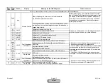
08
Flue Gas Temp
too high
Flue gas temperature outside the permissible value range
Increase parameter
MaxTempFlGasGas(Oil)
or
decrease flue gas temperature.
0A
QGO in Heating-
up Phase
QGO probe not yet sufficiently heated up
Check the temperature of the O2 Sensor via parameter
QGO SensorTemp
. The sensor needs to be a
minumum of 1202
°
F to operate properly. Wait up to 20
minutes for sensor to reach operating termpeature.
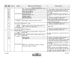
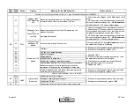
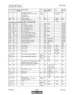
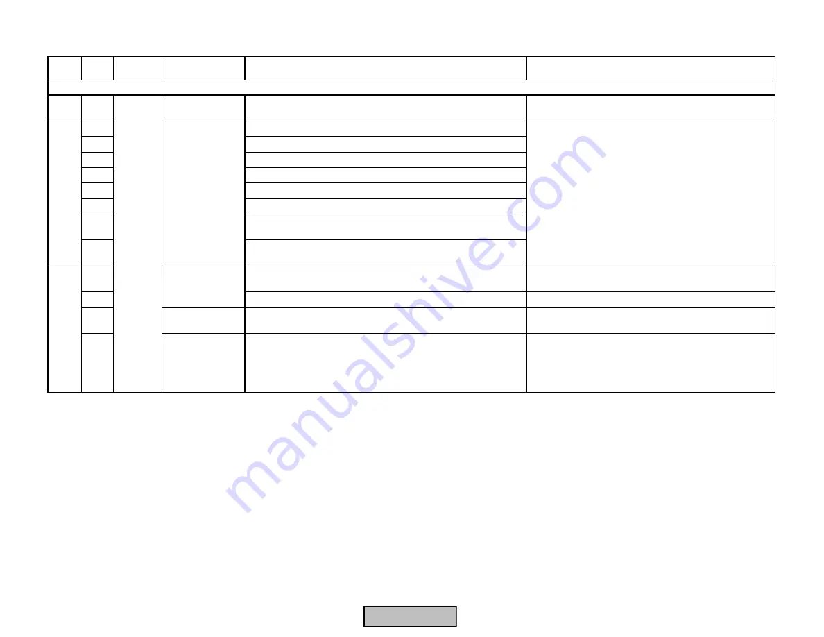
Fault with Base Unit (LMV5) or Connected Components
F1
Internal Fault
Basic Unit
1) Check to make sure that all curves (Ratio control, O2
guard, and O2 control) are defined at every point in the
firing range. If the ratio control curve has 12 points, the
O2 guard must have 12 points, and the O2 trim must
have 11 points.
LMV5
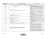
F2
Internal Fault
Basic Unit
Section 7
Page 58
SCC Inc.
HOME
HOME
Summary of Contents for LMV 5 Series
Page 2: ...Intentionally Left Blank ...
Page 41: ...LMV Series Technical Instructions Document No LV5 1000 SCC Inc Page 7 Section 2 HOME ...
Page 42: ...Technical Instructions LMV Series Document No LV5 1000 Section 2 Page 8 SCC Inc HOME ...
Page 43: ...LMV Series Technical Instructions Document No LV5 1000 SCC Inc Page 9 Section 2 HOME ...
Page 44: ...Technical Instructions LMV Series Document No LV5 1000 Section 2 Page 10 SCC Inc HOME ...
Page 45: ...LMV Series Technical Instructions Document No LV5 1000 SCC Inc Page 11 Section 2 HOME ...
Page 46: ...Technical Instructions LMV Series Document No LV5 1000 Section 2 Page 12 SCC Inc HOME ...
Page 47: ...LMV Series Technical Instructions Document No LV5 1000 SCC Inc Page 13 Section 2 HOME ...
Page 48: ...Technical Instructions LMV Series Document No LV5 1000 Section 2 Page 14 SCC Inc HOME ...
Page 49: ...LMV Series Technical Instructions Document No LV5 1000 SCC Inc Page 15 Section 2 HOME ...
Page 50: ...Technical Instructions LMV Series Document No LV5 1000 Section 2 Page 16 SCC Inc HOME ...
Page 51: ...LMV Series Technical Instructions Document No LV5 1000 SCC Inc Page 17 Section 2 HOME ...
Page 52: ...Technical Instructions LMV Series Document No LV5 1000 Section 2 Page 18 SCC Inc HOME ...
Page 53: ...LMV Series Technical Instructions Document No LV5 1000 SCC Inc Page 19 Section 2 HOME ...
Page 54: ...Technical Instructions LMV Series Document No LV5 1000 Section 2 Page 20 SCC Inc HOME ...
Page 55: ...LMV Series Technical Instructions Document No LV5 1000 SCC Inc Page 21 Section 2 HOME ...
Page 373: ...Intentionally Left Blank ...