

Technical
Instructions
LMV
Series
Document
No.
LV5
‐
1000
Section
6
Page
24
SCC
Inc.
O2InitOffset
‐
For
the
other
three
start
modes
other
than
"standard",
this
is
a
rich
or
lean
bias
that
is
applied
to
the
temperature
compensation.
Negative
values
(
‐
2
to
‐
0.1)
will
bias
the
temperature
compensation
more
rich,
and
positive
values
(0.1
to
2)
will
bias
the
temperature
compensation
more
lean.
Note
that
the
units
on
this
are
%O
2
,
so
a
setting
of
‐
2
will
offset
the
O
2
approximately
2%
more
rich.
This
offset
is
dissolved
after
the
O
2
trim
becomes
active
(
NumberTauSuspend
expires).
Menu
path:
Params
&
Display
>
O2Contr/Alarm
>
Gas
Settings
>
Startmode
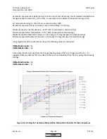
Observing
the
Behavior
of
the
O
2
Trim
After
the
O
2
curves
are
commissioned
and
post
commissioning
tuning
is
done,
the
behavior
of
the
O
2
trim
can
be
observed
and
evaluated
to
determine
if
further
tuning
is
necessary.
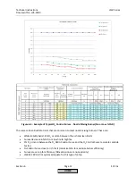
Current
O2
Value
and
O2
Setpoint
Menu
path:
Operation
>
O2
Module
Parameters
can
be
toggled
between
to
see
how
well
the
O
2
setpoint
is
being
followed
at
different
firing
rates
and
when
transitioning
between
firing
rates.
Expected
behavior:
the
difference
between
the
O
2
setpoint
and
actual
value
should
be
slightly
more
when
the
burner
is
transitioning
between
firing
rates
and
less
when
not
transitioning.
As
a
guideline,
the
difference
should
be
less
than
+/
‐
0.2%
O
2
when
not
transitioning
and
less
than
+/
‐
0.4%
O
2
when
transitioning.
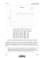
ManVar
O2
Ctrl
Menu
path:
Params
&
Display
>
O2
Contr/Alarm
>
Process
Data
This
parameter
shows
the
amount
of
trim.
The
value
shown
is
defined
below:
1.
A
value
of
50%
indicates
no
trimming.
2.
Values
greater
than
50%
‐
more
air
is
needed
to
achieve
O
2
setpoint
compared
to
when
the
O
2
Control
Curve
was
commissioned.
3.
Values
less
than
50%
‐
less
air
is
needed
to
achieve
O
2
setpoint
compared
to
when
O
2
Control
Curve
was
commissioned.
Expected
behavior:
should
stay
relatively
consistent
from
low
fire
to
high
fire.
Should
change
with
external
changes
such
as
combustion
air
temperature,
barometric
pressure,
draft,
heating
value
of
fuel,
air
filters
becoming
dirty,
etc.
State
O2
Ctrl
Menu
path:
Params
&
Display
>
O2
Contr/Alarm
>
Process
Data
This
parameters
identifies
the
state
of
the
O
2
control.
Possible
values
are:
1.
Deactivated
–
the
O
2
control
was
either
manually
or
automatically
deactivated
2.
Locked
–
the
manipulated
variable
(amount
of
trim)
is
being
held
at
the
last
value
3.
LockTStart
–
O
2
control
is
waiting
to
engage
after
light
‐
off
(waiting
for
NumberTauSuspend
to
expire)
HOME
Summary of Contents for LMV 5 Series
Page 2: ...Intentionally Left Blank ...
Page 41: ...LMV Series Technical Instructions Document No LV5 1000 SCC Inc Page 7 Section 2 HOME ...
Page 42: ...Technical Instructions LMV Series Document No LV5 1000 Section 2 Page 8 SCC Inc HOME ...
Page 43: ...LMV Series Technical Instructions Document No LV5 1000 SCC Inc Page 9 Section 2 HOME ...
Page 44: ...Technical Instructions LMV Series Document No LV5 1000 Section 2 Page 10 SCC Inc HOME ...
Page 45: ...LMV Series Technical Instructions Document No LV5 1000 SCC Inc Page 11 Section 2 HOME ...
Page 46: ...Technical Instructions LMV Series Document No LV5 1000 Section 2 Page 12 SCC Inc HOME ...
Page 47: ...LMV Series Technical Instructions Document No LV5 1000 SCC Inc Page 13 Section 2 HOME ...
Page 48: ...Technical Instructions LMV Series Document No LV5 1000 Section 2 Page 14 SCC Inc HOME ...
Page 49: ...LMV Series Technical Instructions Document No LV5 1000 SCC Inc Page 15 Section 2 HOME ...
Page 50: ...Technical Instructions LMV Series Document No LV5 1000 Section 2 Page 16 SCC Inc HOME ...
Page 51: ...LMV Series Technical Instructions Document No LV5 1000 SCC Inc Page 17 Section 2 HOME ...
Page 52: ...Technical Instructions LMV Series Document No LV5 1000 Section 2 Page 18 SCC Inc HOME ...
Page 53: ...LMV Series Technical Instructions Document No LV5 1000 SCC Inc Page 19 Section 2 HOME ...
Page 54: ...Technical Instructions LMV Series Document No LV5 1000 Section 2 Page 20 SCC Inc HOME ...
Page 55: ...LMV Series Technical Instructions Document No LV5 1000 SCC Inc Page 21 Section 2 HOME ...
Page 373: ...Intentionally Left Blank ...