


Technical
Instructions
LMV
Series
Document
No.
LV5
‐
1000
Section
4
Page
26
SCC
Inc.
d.
Temperature
/
Time
‐
based
Stepping
Start
Combination
This
method
combines
methods
b
and
c
and
if
set
correctly,
is
the
fastest
way
to
safely
warm
the
boiler.
The
settings
are
similar
to
method
b
,
but
now
parameter
MaxTmeMod
is
set
to
have
an
effect
(10
minutes
for
example).
When
this
is
done,
the
maximum
time
that
a
step
‐
up
in
load
will
take
is
10
minutes,
regardless
of
the
temperature
change.
If
the
temperature
change
defined
by
StageSetp_Mod
happens
before
the
10
minutes
elapses,
then
the
temperature
change
will
trigger
the
step
‐
up
in
load.
When
this
mode
is
used,
time
usually
triggers
the
load
steps
at
the
start
of
boiler
warming
and
temperature
change
usually
triggers
the
load
steps
closer
to
the
ThresholdOff
temperature.
This
is
due
to
the
more
rapid
rise
in
boiler
temperature
at
higher
firing
rates.
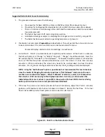
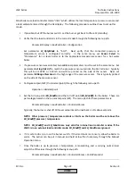
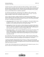
5.
After
parameters
are
set
for
one
of
the
methods
above,
set
parameter
ColdStartOn
to
activated.
The
next
time
the
burner
is
started
and
the
water
temperature
is
below
the
ThresholdOn
temperature,
cold
start
should
engage.
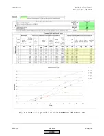
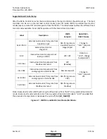
Below
are
typical
settings
for
each
of
the
four
ways
cold
start
can
be
set
up.
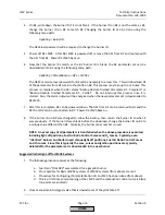
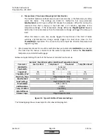
Example:
Steam
Boiler
with
an
Additional
Temperature
Sensor
Parameter
Low
Fire
Hold
Temp
‐
based
Time
‐
based
Temp/time
‐
based
ColdStartOn
Activated
ThresholdOn
50%
(=
150°F)
StageLoad
0%
5%
5%
5%
StageSetp_Mod
N/A
5%
100%
10%
StageSetp_Stage
Staged
Operation
Only
MaxTmeMod
N/A
63
min
5
min
10
min
MaxTmeStage
Staged
Operation
Only
ThresholdOff
80%
(=
240°F)
AdditionalSens
Pt1000
Temp.
ColdStart
Read
Only
Setp
AddSensor
300°F
Release
Stages
Staged
Operation
Only
Figure
4
‐
8:
Typical
Cold
Start
Parameter
Settings
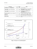
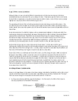
The
following
page
shows
an
example
of
a
time
‐
based
stepping
start.
HOME
Summary of Contents for LMV 5 Series
Page 2: ...Intentionally Left Blank ...
Page 41: ...LMV Series Technical Instructions Document No LV5 1000 SCC Inc Page 7 Section 2 HOME ...
Page 42: ...Technical Instructions LMV Series Document No LV5 1000 Section 2 Page 8 SCC Inc HOME ...
Page 43: ...LMV Series Technical Instructions Document No LV5 1000 SCC Inc Page 9 Section 2 HOME ...
Page 44: ...Technical Instructions LMV Series Document No LV5 1000 Section 2 Page 10 SCC Inc HOME ...
Page 45: ...LMV Series Technical Instructions Document No LV5 1000 SCC Inc Page 11 Section 2 HOME ...
Page 46: ...Technical Instructions LMV Series Document No LV5 1000 Section 2 Page 12 SCC Inc HOME ...
Page 47: ...LMV Series Technical Instructions Document No LV5 1000 SCC Inc Page 13 Section 2 HOME ...
Page 48: ...Technical Instructions LMV Series Document No LV5 1000 Section 2 Page 14 SCC Inc HOME ...
Page 49: ...LMV Series Technical Instructions Document No LV5 1000 SCC Inc Page 15 Section 2 HOME ...
Page 50: ...Technical Instructions LMV Series Document No LV5 1000 Section 2 Page 16 SCC Inc HOME ...
Page 51: ...LMV Series Technical Instructions Document No LV5 1000 SCC Inc Page 17 Section 2 HOME ...
Page 52: ...Technical Instructions LMV Series Document No LV5 1000 Section 2 Page 18 SCC Inc HOME ...
Page 53: ...LMV Series Technical Instructions Document No LV5 1000 SCC Inc Page 19 Section 2 HOME ...
Page 54: ...Technical Instructions LMV Series Document No LV5 1000 Section 2 Page 20 SCC Inc HOME ...
Page 55: ...LMV Series Technical Instructions Document No LV5 1000 SCC Inc Page 21 Section 2 HOME ...
Page 373: ...Intentionally Left Blank ...