
LMV
Series
Technical
Instructions
Document
No.
LV5
‐
1000
SCC
Inc.
Page
17
Section
6
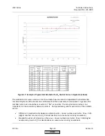
b.
Make
the
burner
drive
to
Point
2
immediately
after
light
off.
This
can
be
done
by
setting
parameter
StartPointOp
to
2
using
the
following
menu
path:
Params
&
Display
>
RatioControl
>
Gas
Settings
>
StartPointOp
=
2
18.
If
the
burner
needs
air
temperature
compensation
after
light
off
(most
ultra
‐
low
NOx
mesh
burners),
activate
air
temperature
compensation.
Multiple
modes
of
temperature
compensation
are
available;
the
most
often
used
mode
is
“IgnPtWithTC”.
This
mode
will
enable
temperature
compensation
after
light
off
and
at
Point
2
before
the
O
2
trim
engages.
Temperature
compensated
light
off
can
be
activated
using
the
following
menu
path:
Params
&
Display
>
O2Contr/Alarm
>
Gas
Settings
>
Startmode
>
Startmode
NOTE:
Air
temperature
compensation
requires
an
air
temperature
sensor
wired
to
the
LMV52.440.
See
“
O
2
Trim
Configuration
(Parameterization)
Before
Commissioning”
above
for
more
information.
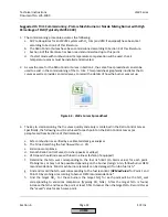
19.
The
O
2
trim
can
now
be
activated
in
one
of
two
modes.
Mode
“conAutoDeac”
allows
the
O
2
trim
to
work
as
long
as
the
measured
%O
2
does
not
exceed
the
rich
limit
(
O
2
Alarm
)
or
the
lean
limit
(
O
2
MaxValue).
If
either
of
these
limits
is
exceeded,
the
O
2
trim
will
deactivate
and
the
burner
will
run
on
the
normal
Ratio
Control
Curves.
Mode
“O2
Control”
also
allows
the
O
2
trim
to
work,
except
that
if
the
limits
are
exceeded
a
lockout
will
occur.
Mode
“conAutoDeac”
is
typically
used.
To
set
the
O
2
control
operating
mode,
use
the
following
menu
path:
Params
&
Display
>
O2Contr/Alarm
>
Gas
Settings
>
OptgMode
20.
The
O
2
trim
is
now
commissioned
and
activated.
Some
additional
tuning
may
be
required
depending
on
the
application.
See
"Post
Commissioning
Tuning"
later
in
this
section
for
more
information.
HOME
Summary of Contents for LMV 5 Series
Page 2: ...Intentionally Left Blank ...
Page 41: ...LMV Series Technical Instructions Document No LV5 1000 SCC Inc Page 7 Section 2 HOME ...
Page 42: ...Technical Instructions LMV Series Document No LV5 1000 Section 2 Page 8 SCC Inc HOME ...
Page 43: ...LMV Series Technical Instructions Document No LV5 1000 SCC Inc Page 9 Section 2 HOME ...
Page 44: ...Technical Instructions LMV Series Document No LV5 1000 Section 2 Page 10 SCC Inc HOME ...
Page 45: ...LMV Series Technical Instructions Document No LV5 1000 SCC Inc Page 11 Section 2 HOME ...
Page 46: ...Technical Instructions LMV Series Document No LV5 1000 Section 2 Page 12 SCC Inc HOME ...
Page 47: ...LMV Series Technical Instructions Document No LV5 1000 SCC Inc Page 13 Section 2 HOME ...
Page 48: ...Technical Instructions LMV Series Document No LV5 1000 Section 2 Page 14 SCC Inc HOME ...
Page 49: ...LMV Series Technical Instructions Document No LV5 1000 SCC Inc Page 15 Section 2 HOME ...
Page 50: ...Technical Instructions LMV Series Document No LV5 1000 Section 2 Page 16 SCC Inc HOME ...
Page 51: ...LMV Series Technical Instructions Document No LV5 1000 SCC Inc Page 17 Section 2 HOME ...
Page 52: ...Technical Instructions LMV Series Document No LV5 1000 Section 2 Page 18 SCC Inc HOME ...
Page 53: ...LMV Series Technical Instructions Document No LV5 1000 SCC Inc Page 19 Section 2 HOME ...
Page 54: ...Technical Instructions LMV Series Document No LV5 1000 Section 2 Page 20 SCC Inc HOME ...
Page 55: ...LMV Series Technical Instructions Document No LV5 1000 SCC Inc Page 21 Section 2 HOME ...
Page 373: ...Intentionally Left Blank ...