


LMV Series
Technical Instructions
Document No. LV5-1000
SCC Inc.
Page 11
Section 9
9-7: Saving and Viewing Trends
The ACS450 software can be used to view and save trends. Trending enables a technician to
easily view and quantify system behavior over time. This feature is particularly useful for setting
up PID loops since “hunting” can be easily recognized on a trend. The following steps outline
the procedure for viewing and saving trends with the ACS450 software:
1.
Connect to the AZL5 at any access level. See Section 9-3 if necessary. After the connection
is established, go to the “System LMV5x” dropdown menu and select “Record Trending”. A
window will appear asking where the trending files are to be saved. Type an appropriate file
name in front of the .tbd extension. A valid file name would look like: siemens.tdb. Notice that
the * is no longer in the file name.
2.
After the file name is typed in, click on “Open”. Click on “Yes” when the window appears
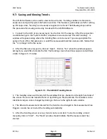
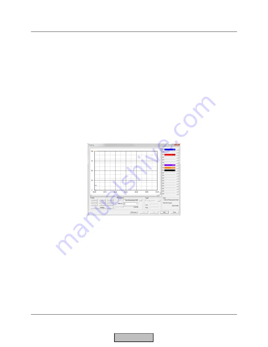
asking if you would like to create the file. The trending screen should now appear and will look
similar to Figure 9-7.1 below.
Figure 9-7.1: The ACS450 Trending Screen
3.
The trending screen will trend all of the variables that are checked on the right hand side of
the screen. These can be turned off and on by clicking on the checkmark. The variables can be
identified and pen colors changed by clicking in the box to the right of each variable.
4.
The title and measurement interval for the trend can be changed in the measurement box.
Triggers can also be set to start the trending automatically.
5.
After the trending screen is set up, trends can be recorded. To start recording a trend
manually, click on “Start”. The “State” window should indicate that the measurement has
started.
HOME
Summary of Contents for LMV 5 Series
Page 2: ...Intentionally Left Blank ...
Page 41: ...LMV Series Technical Instructions Document No LV5 1000 SCC Inc Page 7 Section 2 HOME ...
Page 42: ...Technical Instructions LMV Series Document No LV5 1000 Section 2 Page 8 SCC Inc HOME ...
Page 43: ...LMV Series Technical Instructions Document No LV5 1000 SCC Inc Page 9 Section 2 HOME ...
Page 44: ...Technical Instructions LMV Series Document No LV5 1000 Section 2 Page 10 SCC Inc HOME ...
Page 45: ...LMV Series Technical Instructions Document No LV5 1000 SCC Inc Page 11 Section 2 HOME ...
Page 46: ...Technical Instructions LMV Series Document No LV5 1000 Section 2 Page 12 SCC Inc HOME ...
Page 47: ...LMV Series Technical Instructions Document No LV5 1000 SCC Inc Page 13 Section 2 HOME ...
Page 48: ...Technical Instructions LMV Series Document No LV5 1000 Section 2 Page 14 SCC Inc HOME ...
Page 49: ...LMV Series Technical Instructions Document No LV5 1000 SCC Inc Page 15 Section 2 HOME ...
Page 50: ...Technical Instructions LMV Series Document No LV5 1000 Section 2 Page 16 SCC Inc HOME ...
Page 51: ...LMV Series Technical Instructions Document No LV5 1000 SCC Inc Page 17 Section 2 HOME ...
Page 52: ...Technical Instructions LMV Series Document No LV5 1000 Section 2 Page 18 SCC Inc HOME ...
Page 53: ...LMV Series Technical Instructions Document No LV5 1000 SCC Inc Page 19 Section 2 HOME ...
Page 54: ...Technical Instructions LMV Series Document No LV5 1000 Section 2 Page 20 SCC Inc HOME ...
Page 55: ...LMV Series Technical Instructions Document No LV5 1000 SCC Inc Page 21 Section 2 HOME ...
Page 373: ...Intentionally Left Blank ...