
Technical Instructions
LMV Series
Document No. LV5-1000
Section 10
Page 18
SCC Inc.
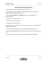
AZL5 Software Update: Version 0460 to 0480
The following updates were made with AZL5 software version 0480:
1. In connection with the new LMV52.4, only AZL5 units with software version 0480 and higher
can be used. The AZL5 can also be used with all other types of LMV5. Due to the new
parameters, the initially reserved storage space in the AZL5 had been exceeded. For this
reason, specific product numbers had to be introduced for the LMV52.4.
2. Change to function
Modulating curve parameterization.
The temperature currently acquired
by the flue gas recirculation (FGR) sensor is
displayed if the flue gas recirculation (FGR) function
is activated and the auxiliary 3 actuator has been selected for FGR.
3. New parameters
OperationTempGas
and
OperationTempOil
are available for reading and
displaying the recorded flue gas recirculation (FGR) temperatures during commissioning.
4. Reading and display of the temperature currently acquired by the flue gas recirculation (FGR)
sensor when the AZL5 is in interface mode. This is provided because the value is not displayed
by the PC tool ACS450.
5. Support of the new flue gas recirculation (FGR) parameters.
6. The AZL5 accepts backup data from older software versions (both AZL5 and ACS450
backups).
7. To avoid misunderstandings, two names have been changed for the FGR operating mode:
•
Aux3onCurve -
When this operating mode is selected, the flue gas recirculation (FGR)
function is deactivated and the auxiliary 3 actuator is driven to the ratio control curve.
This means that if the auxiliary 3 actuator is used as a flue gas feedback actuator, flue
gas would be recirculated.
•
deactMinpos -
Since the word
deact
was replaced by
Aux3oncurve,
the word
deact
is
added here. This denotes that the auxiliary 3 actuator is driven to the minimum position
so that no flue gas is recirculated (or only very small amounts).
8. The cold start thermal shock ON and OFF values are now also displayed as absolute values –
in addition to the relative values.
HOME
Summary of Contents for LMV 5 Series
Page 2: ...Intentionally Left Blank ...
Page 41: ...LMV Series Technical Instructions Document No LV5 1000 SCC Inc Page 7 Section 2 HOME ...
Page 42: ...Technical Instructions LMV Series Document No LV5 1000 Section 2 Page 8 SCC Inc HOME ...
Page 43: ...LMV Series Technical Instructions Document No LV5 1000 SCC Inc Page 9 Section 2 HOME ...
Page 44: ...Technical Instructions LMV Series Document No LV5 1000 Section 2 Page 10 SCC Inc HOME ...
Page 45: ...LMV Series Technical Instructions Document No LV5 1000 SCC Inc Page 11 Section 2 HOME ...
Page 46: ...Technical Instructions LMV Series Document No LV5 1000 Section 2 Page 12 SCC Inc HOME ...
Page 47: ...LMV Series Technical Instructions Document No LV5 1000 SCC Inc Page 13 Section 2 HOME ...
Page 48: ...Technical Instructions LMV Series Document No LV5 1000 Section 2 Page 14 SCC Inc HOME ...
Page 49: ...LMV Series Technical Instructions Document No LV5 1000 SCC Inc Page 15 Section 2 HOME ...
Page 50: ...Technical Instructions LMV Series Document No LV5 1000 Section 2 Page 16 SCC Inc HOME ...
Page 51: ...LMV Series Technical Instructions Document No LV5 1000 SCC Inc Page 17 Section 2 HOME ...
Page 52: ...Technical Instructions LMV Series Document No LV5 1000 Section 2 Page 18 SCC Inc HOME ...
Page 53: ...LMV Series Technical Instructions Document No LV5 1000 SCC Inc Page 19 Section 2 HOME ...
Page 54: ...Technical Instructions LMV Series Document No LV5 1000 Section 2 Page 20 SCC Inc HOME ...
Page 55: ...LMV Series Technical Instructions Document No LV5 1000 SCC Inc Page 21 Section 2 HOME ...
Page 373: ...Intentionally Left Blank ...