


Technical
Instructions
LMV
Series
Document
No.
LV5
‐
1000
Section
4
Page
20
SCC
Inc.
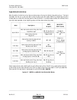
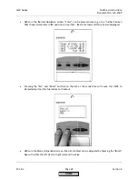
NOTE:
When
in
a
curve
point
on
the
right
‐
hand
side
of
the
AZL
screen,
pressing
“Esc”
will
bring
the
cursor
back
to
the
left,
off
of
the
numbers.
Pressing
“Esc”
again
while
off
of
the
numbers
will
bring
up
a
prompt
to
ask
if
the
point
is
to
be
stored
(press
“Enter”)
or
the
changes
canceled
(press
“Esc”).
If
store
is
selected,
a
bar
will
rotate
on
the
left
‐
hand
side
of
the
AZL5
display
while
the
point
is
being
stored.
NOTE:
When
putting
in
a
new
point
that
is
not
yet
defined
(XXXX
shown
for
the
positions
and
load),
pressing
“Enter”
will
put
in
values
for
the
positions
and
load
from
the
previous
point
based
on
load
number.
These
values
serve
as
a
place
to
start
for
the
new
point.
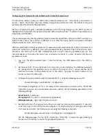
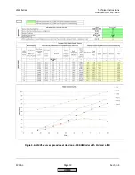
9.
With
the
Ratio
Control
Curves
laid
out
on
paper
or
with
the
spreadsheet,
begin
setting
the
curve
points
from
low
fire
(Point
1)
to
high
fire
(Point
10).
The
general
procedure
for
each
point
is
to
match
the
load
number
to
the
fuel
flow
while
maintaining
safe
combustion.
After
this
is
complete,
adjust
the
air
and
/
or
FGR
as
necessary
to
achieve
safe,
efficient
combustion
and
emissions
compliance
on
each
point.
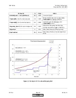
10.
The
following
is
a
summary
of
what
should
be
achieved
for
each
point
on
the
Ratio
Control
Curve:
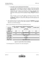
For
standard
burners
(LMV51,
or
LMV52
without
O
2
trim):
a.
Safe,
efficient
combustion
as
verified
by
a
calibrated
stack
gas
analyzer
b.
The
%
load
matching
the
fuel
flow
within
+/
‐
5%
c.
Emissions
compliance
d.
Smooth
Ratio
Control
Curves
(no
sharp
peaks
and
valleys)
For
standard
nozzle
mixing
burners
(no
or
low
%
FGR)
and
O
2
trim
(LMV52):
e.
All
points
a
thru
d
above
f.
VSD
speed
should
increase
with
load
in
a
linear
fashion
(if
equipped)
g.
The
%
load
matching
the
fuel
flow
within
+/
‐
3%
h.
Find
and
record
the
%O
2
wet
corresponding
to
the
fuel
rich
limit
(
O2
Alarm
value)
for
each
point
by
probing*
i.
Find
and
record
the
%O
2
wet
corresponding
to
the
fuel
lean
limit
(
O2
MaxValue
)
for
Point
1
and
Point
10
by
probing*
j.
Last
but
not
least,
leave
the
curve
points
so
that
the
%O
2
wet
is
2%
higher
than
the
fuel
rich
limit
(
O2
Alarm
value).
Record
this
as
the
saved
value
for
each
curve
point.
For
pre
‐
mix
mesh
burners
and
nozzle
mixing
burners
(high
%
FGR)
and
O
2
trim
(LMV52):
k.
All
points
a
thru
d
above
l.
VSD
speed
should
increase
with
load
in
a
linear
fashion
(if
equipped)
m.
The
%
load
matching
the
fuel
flow
within
+/
‐
3%
n.
Determine
the
%O
2
wet
corresponding
to
the
fuel
rich
limit
(
O2
Alarm
Value)
for
each
point.
Probing
may
or
may
not
be
possible
depending
on
the
burner
design.
Also,
follow
burner
OEM
recommendations.
Most
mesh
burner
elements
can
be
damaged
if
run
too
fuel
rich.*
HOME
Summary of Contents for LMV 5 Series
Page 2: ...Intentionally Left Blank ...
Page 41: ...LMV Series Technical Instructions Document No LV5 1000 SCC Inc Page 7 Section 2 HOME ...
Page 42: ...Technical Instructions LMV Series Document No LV5 1000 Section 2 Page 8 SCC Inc HOME ...
Page 43: ...LMV Series Technical Instructions Document No LV5 1000 SCC Inc Page 9 Section 2 HOME ...
Page 44: ...Technical Instructions LMV Series Document No LV5 1000 Section 2 Page 10 SCC Inc HOME ...
Page 45: ...LMV Series Technical Instructions Document No LV5 1000 SCC Inc Page 11 Section 2 HOME ...
Page 46: ...Technical Instructions LMV Series Document No LV5 1000 Section 2 Page 12 SCC Inc HOME ...
Page 47: ...LMV Series Technical Instructions Document No LV5 1000 SCC Inc Page 13 Section 2 HOME ...
Page 48: ...Technical Instructions LMV Series Document No LV5 1000 Section 2 Page 14 SCC Inc HOME ...
Page 49: ...LMV Series Technical Instructions Document No LV5 1000 SCC Inc Page 15 Section 2 HOME ...
Page 50: ...Technical Instructions LMV Series Document No LV5 1000 Section 2 Page 16 SCC Inc HOME ...
Page 51: ...LMV Series Technical Instructions Document No LV5 1000 SCC Inc Page 17 Section 2 HOME ...
Page 52: ...Technical Instructions LMV Series Document No LV5 1000 Section 2 Page 18 SCC Inc HOME ...
Page 53: ...LMV Series Technical Instructions Document No LV5 1000 SCC Inc Page 19 Section 2 HOME ...
Page 54: ...Technical Instructions LMV Series Document No LV5 1000 Section 2 Page 20 SCC Inc HOME ...
Page 55: ...LMV Series Technical Instructions Document No LV5 1000 SCC Inc Page 21 Section 2 HOME ...
Page 373: ...Intentionally Left Blank ...