


LMV
Series
Technical
Instructions
Document
No.
LV5
‐
1000
SCC
Inc.
Page
3
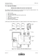
Section
7
CANbus
Faults
Including
“
AZL
not
on
Bus
”
and
“
System
Test
”
(continued)
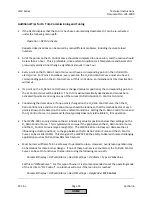
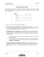
The
most
common
CANbus
errors
are:
“AZL
not
on
Bus”
Stuck
in
“System
Test”
Error
code
99
Error
code
A7,
diagnostic
17
However,
there
are
many
additional
error
codes
that
can
also
be
caused
by
an
issue
with
the
CANbus
network.
The
following
procedure
can
be
used
to
diagnose
any
CANbus
related
error:
1.
Take
the
cover
off
of
the
last
actuator
(or
PLL52
O
2
module)
on
the
CANbus
network
wired
to
terminal
X51
on
the
LMV5.
This
should
have
only
one
5
‐
pin
green
connector
plugged
into
it.
The
other
CANbus
terminals
should
be
empty,
and
is
a
perfect
place
to
measure
voltage.
Ensure
that
the
following
voltages
are
present
on
the
pins
of
the
empty
CANbus
terminal:
12
VAC
between
pins
12VAC1
and
GND
12
VAC
between
pins
12VAC2
and
GND
24
VAC
between
pins
12VAC1
and
12VAC2
When
measuring
to
ground
(GND),
it
is
ok
to
have
anywhere
from
10.2
‐
13.2
VAC
as
long
as
both
measurements
are
the
same.
For
example,
it
is
okay
to
have
11
VAC
between
pins
12VAC1
and
GND
as
long
as
there
is
also
11
VAC
between
pins
12VAC2
and
GND.
In
addition,
the
voltage
between
pins
12VAC1
and
12VAC2
must
be
exactly
double
the
other
two
measurements.
If
these
three
voltage
measurements
are
correct,
skip
to
step
3.
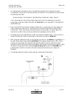
2.
If
one
or
more
of
the
voltage
measurements
is
incorrect,
check
the
following:
CANbus
fuses
FU2
and
FU3
are
located
on
the
right
hand
side
of
the
LMV5.
Check
that
these
fuses
are
not
blown.
If
either
one
is
blown,
check
the
LMV5
wiring
for
incorrect
terminations.
Once
any
wiring
errors
have
been
fixed,
replace
the
blown
fuse.
The
most
common
wiring
error
has
to
do
with
pins
3
and
4
on
transformer
terminal
SEK2.
Pin
3
on
terminal
SEK2
should
be
wired
to
terminal
X52,
pin
4
on
the
LMV5.
Pin
4
on
terminal
SEK2
should
be
wired
to
terminal
X52,
pin
3
on
the
LMV5.
Make
sure
pin
3
on
terminal
SEK2
of
the
transformer
is
grounded
properly.
Make
sure
the
rest
of
the
CANbus
network
is
wired
properly.
See
Section
2
for
additional
wiring
assistance.
HOME
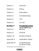
Summary of Contents for LMV 5 Series
Page 2: ...Intentionally Left Blank ...
Page 41: ...LMV Series Technical Instructions Document No LV5 1000 SCC Inc Page 7 Section 2 HOME ...
Page 42: ...Technical Instructions LMV Series Document No LV5 1000 Section 2 Page 8 SCC Inc HOME ...
Page 43: ...LMV Series Technical Instructions Document No LV5 1000 SCC Inc Page 9 Section 2 HOME ...
Page 44: ...Technical Instructions LMV Series Document No LV5 1000 Section 2 Page 10 SCC Inc HOME ...
Page 45: ...LMV Series Technical Instructions Document No LV5 1000 SCC Inc Page 11 Section 2 HOME ...
Page 46: ...Technical Instructions LMV Series Document No LV5 1000 Section 2 Page 12 SCC Inc HOME ...
Page 47: ...LMV Series Technical Instructions Document No LV5 1000 SCC Inc Page 13 Section 2 HOME ...
Page 48: ...Technical Instructions LMV Series Document No LV5 1000 Section 2 Page 14 SCC Inc HOME ...
Page 49: ...LMV Series Technical Instructions Document No LV5 1000 SCC Inc Page 15 Section 2 HOME ...
Page 50: ...Technical Instructions LMV Series Document No LV5 1000 Section 2 Page 16 SCC Inc HOME ...
Page 51: ...LMV Series Technical Instructions Document No LV5 1000 SCC Inc Page 17 Section 2 HOME ...
Page 52: ...Technical Instructions LMV Series Document No LV5 1000 Section 2 Page 18 SCC Inc HOME ...
Page 53: ...LMV Series Technical Instructions Document No LV5 1000 SCC Inc Page 19 Section 2 HOME ...
Page 54: ...Technical Instructions LMV Series Document No LV5 1000 Section 2 Page 20 SCC Inc HOME ...
Page 55: ...LMV Series Technical Instructions Document No LV5 1000 SCC Inc Page 21 Section 2 HOME ...
Page 373: ...Intentionally Left Blank ...