


Technical
Instructions
LMV
Series
Document
No.
LV5
‐
1000
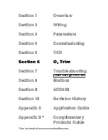
Section
6
Page
2
SCC
Inc.
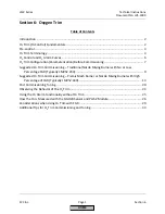
Introduction
The
LMV52.240
and
the
LMV52.440
both
have
O
2
(oxygen)
trim
and
O
2
alarm
(previously
called
“monitor”)
capability.
In
addition,
the
LMV52.440
offers
advanced
features
such
as
temperature
compensated
light
‐
off
and
more
dynamic
O
2
trim
capabilities.
In
general,
the
LMV52.440
is
recommended
for
more
difficult
applications
such
as
low
and
ultra
‐
low
NOx
burners
where
the
burner
stability
band
is
much
smaller
than
a
traditional
nozzle
mixing
burner.
Some
features
in
the
LMV52.440
were
specifically
designed
for
ultra
‐
low
NOx
mesh
burners.
The
O
2
trim
functions
by
using
an
in
‐
situ
O
2
sensor
installed
in
the
boiler
stack,
and
then
adjusting
actuators
and
/
or
VSD
to
maintain
a
%
O
2
setpoint.
Only
air
‐
related
(air
influenced)
actuators
are
adjusted,
thus
the
O
2
trim
does
not
adjust
the
firing
rate
(fuel
‐
related
load).
Only
the
air
rate
(air
‐
related
load)
is
adjusted.
Each
Ratio
Control
Curve
Point
that
is
entered
(see
Section
4)
will
have
a
corresponding
O
2
trim
setpoint,
rich
limit
(O
2
alarm)
and
lean
limit
(O
2
max
value).
The
exception
to
this
rule
is
that
O
2
trim
cannot
be
performed
on
Point
1.
If
10
points
are
entered
on
the
Ratio
Control
Curve,
there
will
be
9
trim
points
and
10
rich
limit
(O
2
alarm)
points.
Having
10
points
on
the
Ratio
Control
Curve
is
recommended.
As
is
the
case
with
advanced
systems
such
as
O
2
trim,
the
fundamental
systems
that
lie
underneath
the
advanced
system
must
be
in
place
and
working
correctly
to
enable
the
advanced
system
to
work
correctly.
For
example,
if
the
gas
pressure
supply
is
not
repeatable
upstream
of
the
firing
rate
control
valve
(fundamental
system),
then
the
O
2
trim
(advanced
system)
is
likely
to
deactivate.
The
fundamental
systems
on
the
burner
/
boiler
that
must
be
working
correctly
are
outlined
in
detail
in
the
Pre
‐
Requisites
listed
in
Section
4.
The
Pre
‐
Requisites
for
LMV52
systems
with
O
2
trim
must
be
met
before
O
2
trim
commissioning
is
attempted.
If
the
Pre
‐
Requisites
are
satisfied,
then
reliable
operation
of
the
O
2
trim
depends
on
correct
parameter
settings
for
the
application
and
correct
commissioning
of
the
O
2
trim.
This
section
will
outline
the
basics
behind
how
the
O
2
trim
system
operates,
and
will
outline
the
typical
commissioning
procedure
for
a
traditional
nozzle
mixing
burner
(standard
emissions)
and
a
pre
‐
mix
mesh
burner
(low
or
ultra
‐
low
NOx).
Nozzle
mixing
burners
that
use
a
high
percentage
of
FGR
to
achieve
low
NOx
typically
behave
in
a
way
that
is
similar
to
a
pre
‐
mix
mesh
burner,
so
the
commissioning
procedure
for
these
types
of
burners
is
similar
to
a
pre
‐
mix
mesh
burner.
O
2
Trim
(O
2
Control)
Fundamentals
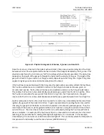
By
definition,
an
O
2
trim
(O
2
control)
system
monitors
the
level
of
O
2
in
the
exhaust
gases
of
the
boiler
and
adjusts
the
fuel
or
air
flow
to
maintain
an
O
2
setpoint.
The
LMV52
accomplishes
this
task
by
reading
the
%O
2
(wet
basis)
with
an
in
‐
situ
O
2
sensor
and
by
adjusting
the
angular
position
of
air
flow
influencing
actuators.
If
the
burner
is
equipped
with
a
VSD
(variable
speed
drive)
for
the
blower,
the
O
2
trim
can
also
adjust
the
blower
speed
to
influence
the
burner
airflow.
HOME
Summary of Contents for LMV 5 Series
Page 2: ...Intentionally Left Blank ...
Page 41: ...LMV Series Technical Instructions Document No LV5 1000 SCC Inc Page 7 Section 2 HOME ...
Page 42: ...Technical Instructions LMV Series Document No LV5 1000 Section 2 Page 8 SCC Inc HOME ...
Page 43: ...LMV Series Technical Instructions Document No LV5 1000 SCC Inc Page 9 Section 2 HOME ...
Page 44: ...Technical Instructions LMV Series Document No LV5 1000 Section 2 Page 10 SCC Inc HOME ...
Page 45: ...LMV Series Technical Instructions Document No LV5 1000 SCC Inc Page 11 Section 2 HOME ...
Page 46: ...Technical Instructions LMV Series Document No LV5 1000 Section 2 Page 12 SCC Inc HOME ...
Page 47: ...LMV Series Technical Instructions Document No LV5 1000 SCC Inc Page 13 Section 2 HOME ...
Page 48: ...Technical Instructions LMV Series Document No LV5 1000 Section 2 Page 14 SCC Inc HOME ...
Page 49: ...LMV Series Technical Instructions Document No LV5 1000 SCC Inc Page 15 Section 2 HOME ...
Page 50: ...Technical Instructions LMV Series Document No LV5 1000 Section 2 Page 16 SCC Inc HOME ...
Page 51: ...LMV Series Technical Instructions Document No LV5 1000 SCC Inc Page 17 Section 2 HOME ...
Page 52: ...Technical Instructions LMV Series Document No LV5 1000 Section 2 Page 18 SCC Inc HOME ...
Page 53: ...LMV Series Technical Instructions Document No LV5 1000 SCC Inc Page 19 Section 2 HOME ...
Page 54: ...Technical Instructions LMV Series Document No LV5 1000 Section 2 Page 20 SCC Inc HOME ...
Page 55: ...LMV Series Technical Instructions Document No LV5 1000 SCC Inc Page 21 Section 2 HOME ...
Page 373: ...Intentionally Left Blank ...