
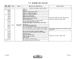
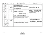
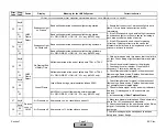
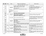

Error
Code
Diag.
Code
Device
Display
Meaning for the LMV5x System
Corrective Action
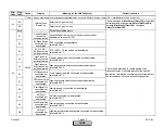
Any #
Fault during test of the flame signal amplifier
01
Fault during test of the flame signal amplifier
02
Crosstalk fault between test pin and flame signal amplifier
channel (with LMV52 FSV channel QRI... / QRB...)
03
Crosstalk fault between test pin and FSV channel ION (LMV52
only)
10
Monitoring of redundancy contact on external high-temperature
or flame safegaurd
Check the wiring and the parameters of the external
safety limit thermostat / external flame safeguard
including the redundancy contact.
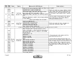
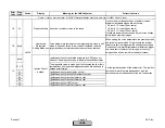
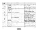
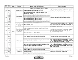
Any #
Fault internal hardware tests
01
Fault during test of the ignition relay
02
Fault during test of the safety relay
03
Fault during voltage supervision test
04
Relay voltage not switched off after reset
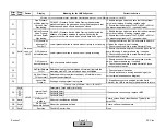
Any #
Basic unit has detected an improper circuit at one of the
outputs, a faulty diode, or a short-circuit in the power supply of
the contact feedback network. The diagnostic code indicates
the input affected.
01
Load controller on / off
02
Fan contact
03
Selection of oil-firing
04
Selection of gas-firing
05
Reset
06
Pressure switch oil maximum
07
Pressure switch oil minimum
08
Pressure switch valve proving
09
Safety valve oil feedback
0A
Fuel valve 1 oil feedback
0B
Fuel valve 2 oil feedback
0C
Fuel valve 3 oil feedback
0D
Safety valve gas feedback
0E
Fuel valve 1 gas feedback
0F
Fuel valve 2 gas feedback
10
Pilot valve gas feedback
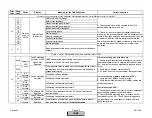
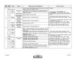
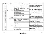
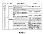
Fault with Base Unit (LMV5)
Internal Fault
Basic Unit
1) Check connections of the neutrals to all of the
connected switches, valves, etc...
2) Check for inductive loads that cause voltage to be
present on the terminal after the LMV de-energizes the
terminal. If voltage exists on an output terminal, such as
a fuel valve, after the LMV de-energizes the terminal,
this will cause a fault. Voltage must drop to zero on the
terminal within about 10 ms after the terminal is de-
energized.
If fault occurs sporadically, reduce electrical noise.
If fault occurs continuously, replace LMV5.
06
LMV5
Internal Fault
Basic Unit
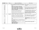
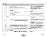
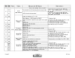
Fault with devices or wiring connected to the Base Unit (LMV5)
LMV5 /
Flame
Dect.
Fault Flame
Detector Test
05
Fault with Flame scanner (QRI) or Base Unit (LMV5)
10
If fault occurs sporadically: Improve shielding / isolation
of flame detector wires. High LMV5 temperatures can
also cause this fault. If fault occurs constantly: Lower
LMV5 temperature, replace flame detector, or replace
LMV5.
Devices
conn. to
LMV5
Section 7
Page 24
SCC Inc.
HOMEHOME
HOME
Summary of Contents for LMV 5 Series
Page 2: ...Intentionally Left Blank ...
Page 41: ...LMV Series Technical Instructions Document No LV5 1000 SCC Inc Page 7 Section 2 HOME ...
Page 42: ...Technical Instructions LMV Series Document No LV5 1000 Section 2 Page 8 SCC Inc HOME ...
Page 43: ...LMV Series Technical Instructions Document No LV5 1000 SCC Inc Page 9 Section 2 HOME ...
Page 44: ...Technical Instructions LMV Series Document No LV5 1000 Section 2 Page 10 SCC Inc HOME ...
Page 45: ...LMV Series Technical Instructions Document No LV5 1000 SCC Inc Page 11 Section 2 HOME ...
Page 46: ...Technical Instructions LMV Series Document No LV5 1000 Section 2 Page 12 SCC Inc HOME ...
Page 47: ...LMV Series Technical Instructions Document No LV5 1000 SCC Inc Page 13 Section 2 HOME ...
Page 48: ...Technical Instructions LMV Series Document No LV5 1000 Section 2 Page 14 SCC Inc HOME ...
Page 49: ...LMV Series Technical Instructions Document No LV5 1000 SCC Inc Page 15 Section 2 HOME ...
Page 50: ...Technical Instructions LMV Series Document No LV5 1000 Section 2 Page 16 SCC Inc HOME ...
Page 51: ...LMV Series Technical Instructions Document No LV5 1000 SCC Inc Page 17 Section 2 HOME ...
Page 52: ...Technical Instructions LMV Series Document No LV5 1000 Section 2 Page 18 SCC Inc HOME ...
Page 53: ...LMV Series Technical Instructions Document No LV5 1000 SCC Inc Page 19 Section 2 HOME ...
Page 54: ...Technical Instructions LMV Series Document No LV5 1000 Section 2 Page 20 SCC Inc HOME ...
Page 55: ...LMV Series Technical Instructions Document No LV5 1000 SCC Inc Page 21 Section 2 HOME ...
Page 373: ...Intentionally Left Blank ...