
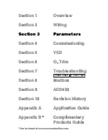


LMV Series
Technical Instructions
LV5-1000
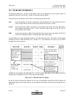
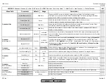
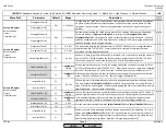
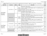
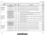
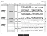
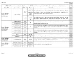
Menu Path
Parameter
Default
Range
Description
51.1
52.2
52.4
LEGEND -
Password Access:
(U)=User, (S)=Service, (O)=OEM, Shaded = Commonly Used, ** = Must Set, X = Has Function, / = Partial Function
LMV
RotSpeed PS on (S)
80%
0-100%
If FGR-PS/FCC is set to PS VSD, then INPUT X4-01.3 must be energized from this % VSD and
higher. Must be set higher than
RotSpeed PS off
.
x x
RotSpeed PS off (S)
50%
0-100%
If FGR-PS/FCC is set to PS VSD, then INPUT X4-01.3 must be de-energized from this % VSD
and lower. Must be set lower than
RotSpeed PS on
.
x x
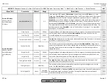
InputController (O)
activated
activated
deactivated
Sets the function of INPUT X5-03.1. If activated, X5-03.1 must be energized to permit the
LMV5 to fire. This setting is typically used with a hardwired burner on-off switch. On an
LMV5 equipped with an internal load controller (LMV51.1 and higher), the internal load
controller may remove the call for heat and shut down the burner even if X5-03.1 is
energized. If deactivated, X5-03.1 has no function when in any internal load control mode.
The LMV5 can also be given permission to fire via Modbus if X5-03.1 is deactivated.
x x x
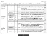
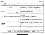
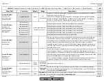
Config X5-03 (S)
LMV5x std
LMV5x std
LMV2/3 std
LMV2/3 inv
DeaO2/Stp36
CoolFctStby
AutoDeactO2
Sets the function of INPUTS X5-03.2 and X5-03.3.
1) LMV5x std - floating bumping load control is retained.
2) LMV2/3 std or LMV2/3 inv - normal or inverted LMV5 2/3 staged oil functionality.
3) DeaO2/Stp36 - energizing terminal X5-03.2 disables O2 trim and de-energizing enables O2
trim (LMV52 only). Also, energizing terminal X5-03.3 allows the LMV5 to progress past phase
36 (de-energizing stops the LMV5 in phase 36 indefinitely).
4) CoolFctStby - only used on an LMV50.
5) AutoDeactO2 - energizing X5-03.2 will deactivate the O2 trim by setting the O2 trim mode
to "auto deact". O2 trim mode must be set to "ConAutoDeac" for the AutoDeactO2 to
function. De-energizing sets trim mode back to "ConAutoDeac".
/ / /
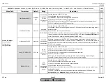
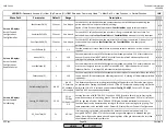
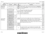
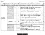
GasPressureMin (O)
activated
activated
deactivated
deact xOGP
Sets the function of INPUT X9-03.4 for the low gas pressure switch.
1) activated - input is expected to be energized when firing gas, or when using any oil train
that requires a gas pilot.
2) deactivated - terminal has no function.
3) deact xOGP - input is expected to be energized only when firing gas.
GasPressureMax (O)
activated
activated
deactivated
Sets the function of INPUT X9-03.3 for a high gas pressure switch. Activate for gas fired
installations that use a high gas pressure switch.
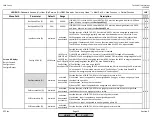
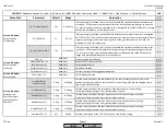
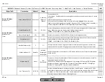
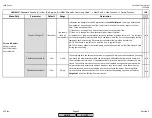
OilPressureMin (O)
activated
activated
deactivated
act from ts
Sets the function of INPUT X5-01.2 for a low oil pressure switch.
1) activated - input is expected to be energized by phase 38.
2) deactivated - terminal has no function.
3) act from ts - input is expected to be energized by phase 40.
OilPressureMax (O)
activated
activated
deactivated
Sets the function of INPUT X5-02.2 for the high oil pressure switch.
x
Params & Display>
BurnerControl>
Configuration>
ConfigIn/Output
x x
SCC Inc.
Page 13
Section 3
HOME
HOME
P - LIST
Summary of Contents for LMV 5 Series
Page 2: ...Intentionally Left Blank ...
Page 41: ...LMV Series Technical Instructions Document No LV5 1000 SCC Inc Page 7 Section 2 HOME ...
Page 42: ...Technical Instructions LMV Series Document No LV5 1000 Section 2 Page 8 SCC Inc HOME ...
Page 43: ...LMV Series Technical Instructions Document No LV5 1000 SCC Inc Page 9 Section 2 HOME ...
Page 44: ...Technical Instructions LMV Series Document No LV5 1000 Section 2 Page 10 SCC Inc HOME ...
Page 45: ...LMV Series Technical Instructions Document No LV5 1000 SCC Inc Page 11 Section 2 HOME ...
Page 46: ...Technical Instructions LMV Series Document No LV5 1000 Section 2 Page 12 SCC Inc HOME ...
Page 47: ...LMV Series Technical Instructions Document No LV5 1000 SCC Inc Page 13 Section 2 HOME ...
Page 48: ...Technical Instructions LMV Series Document No LV5 1000 Section 2 Page 14 SCC Inc HOME ...
Page 49: ...LMV Series Technical Instructions Document No LV5 1000 SCC Inc Page 15 Section 2 HOME ...
Page 50: ...Technical Instructions LMV Series Document No LV5 1000 Section 2 Page 16 SCC Inc HOME ...
Page 51: ...LMV Series Technical Instructions Document No LV5 1000 SCC Inc Page 17 Section 2 HOME ...
Page 52: ...Technical Instructions LMV Series Document No LV5 1000 Section 2 Page 18 SCC Inc HOME ...
Page 53: ...LMV Series Technical Instructions Document No LV5 1000 SCC Inc Page 19 Section 2 HOME ...
Page 54: ...Technical Instructions LMV Series Document No LV5 1000 Section 2 Page 20 SCC Inc HOME ...
Page 55: ...LMV Series Technical Instructions Document No LV5 1000 SCC Inc Page 21 Section 2 HOME ...
Page 373: ...Intentionally Left Blank ...