


LMV Series
Technical Instructions
Document No. LV5-1000
SCC Inc.
Page 13
Section 8
Selection menus in the AZL5
Activation of Modbus operation
Ensure the gateway mode is set to Modbus:
Operation > OptgModeSelect > Type of Gateway
Activation takes place via menu:
Operation > OptgModeSelect > GatewayBASon
Having made the selection, the menu item can be quit via ESC.The setting is retained until
Operation >
OptgModeSelect > GatewayBASoff
is selected via the AZL… menu.
When GatewayBASon is activated, plant operation and diagnostics via the AZL... are still possible.
Deactivation takes place via menu:
Operation > OptgModeSelect > GatewayBASoff
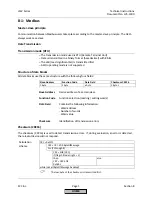
Slave address
Selection is made via menu:
Params & Display > AZL > Modbus > Address
According to Modicon specifications, addresses between 1...247 can be selected. The slave address is
filed in nonvolatile memory of the AZL...
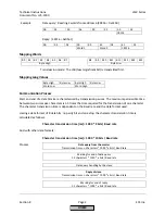
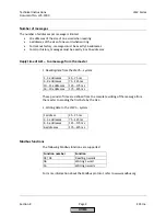
Transmission parameters
Transmission rate
The setting is made via menu:
Params & Display > AZL > Modbus > Baudrate.
There is a choice of 9600 bit/s or 19200 bit/s.
Parity
Using the AZL... menu:
Params & Display > AZL > Modbus > Parity
,
parity can be set to none, even or odd.
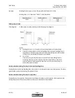
Timeout communication failure
When there is no Modbus communication, this timeout defines the period of time on completion of
which the AZL… changes automatically from Remote to Local.
The setting is made via menu
Params & Display > AZL > Modbus > Timeout
.
Local «-» Remote mode
This setting defines whether the AZL… shall work in Local or Remote mode.
Remote mode
Display of Remote Auto, Remote On, Remote Off mode. A change can only be made via Modbus.
HOME
Summary of Contents for LMV 5 Series
Page 2: ...Intentionally Left Blank ...
Page 41: ...LMV Series Technical Instructions Document No LV5 1000 SCC Inc Page 7 Section 2 HOME ...
Page 42: ...Technical Instructions LMV Series Document No LV5 1000 Section 2 Page 8 SCC Inc HOME ...
Page 43: ...LMV Series Technical Instructions Document No LV5 1000 SCC Inc Page 9 Section 2 HOME ...
Page 44: ...Technical Instructions LMV Series Document No LV5 1000 Section 2 Page 10 SCC Inc HOME ...
Page 45: ...LMV Series Technical Instructions Document No LV5 1000 SCC Inc Page 11 Section 2 HOME ...
Page 46: ...Technical Instructions LMV Series Document No LV5 1000 Section 2 Page 12 SCC Inc HOME ...
Page 47: ...LMV Series Technical Instructions Document No LV5 1000 SCC Inc Page 13 Section 2 HOME ...
Page 48: ...Technical Instructions LMV Series Document No LV5 1000 Section 2 Page 14 SCC Inc HOME ...
Page 49: ...LMV Series Technical Instructions Document No LV5 1000 SCC Inc Page 15 Section 2 HOME ...
Page 50: ...Technical Instructions LMV Series Document No LV5 1000 Section 2 Page 16 SCC Inc HOME ...
Page 51: ...LMV Series Technical Instructions Document No LV5 1000 SCC Inc Page 17 Section 2 HOME ...
Page 52: ...Technical Instructions LMV Series Document No LV5 1000 Section 2 Page 18 SCC Inc HOME ...
Page 53: ...LMV Series Technical Instructions Document No LV5 1000 SCC Inc Page 19 Section 2 HOME ...
Page 54: ...Technical Instructions LMV Series Document No LV5 1000 Section 2 Page 20 SCC Inc HOME ...
Page 55: ...LMV Series Technical Instructions Document No LV5 1000 SCC Inc Page 21 Section 2 HOME ...
Page 373: ...Intentionally Left Blank ...