


Technical
Instructions
LMV
Series
Document
No.
LV5
‐
1000
Section
7
Page
4
SCC
Inc.
CANbus
Faults
Including
“
AZL
not
on
Bus
”
and
“
System
Test
”
(continued)
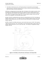
3.
Check
the
LMV5
fault
history.
If
the
faults
always
occur
in
phase
38,
the
CANbus
errors
are
being
caused
by
noise
from
the
ignition
transformer.
Make
sure
the
ignition
transformer
is
grounded
properly
and
has
a
good
neutral.
Also,
make
sure
any
CANbus
wires
that
run
close
to
the
ignition
transformer
are
in
proper
conduit.
It
may
be
necessary
to
either
relocate
the
ignition
transformer
or
add
a
shield
between
the
ignition
transformer
and
any
nearby
CANbus
wires.
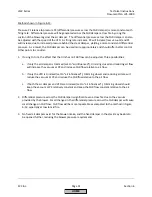
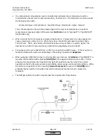
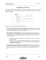
4.
Unplug
the
6
‐
pin
green
connector
plugged
into
terminal
X51
on
the
top
of
the
LMV5.
This
leaves
the
AZL,
the
LMV5,
and
the
cable
between
them
as
the
only
CANbus
components
still
plugged
in.
Reset
the
fault
on
the
LMV5.
At
this
point,
two
things
can
happen:
If
the
AZL
faults
with
“Fault
Feedback
Air
Actuator”,
then
the
AZL,
the
LMV5,
and
the
cable
between
them
are
all
working
properly.
This
means
that
there
is
likely
an
issue
with
the
wiring
of
the
actuators
or
O
2
module.
Go
to
step
5.
If
the
same
CANbus
fault
recurs,
then
there
is
a
problem
with
the
AZL,
the
LMV5,
or
the
cable
between
them.
Check
the
wiring
and
terminations
on
the
cable.
Though
unlikely,
the
AZL
or
the
LMV5
might
be
damaged
and
need
to
be
replaced.
If
a
spare
AZL
is
available,
try
it.
If
no
spare
AZL
is
present,
check
for
any
noticeable
damage
to
either
the
AZL
or
the
LMV5
to
determine
which
component
to
replace.
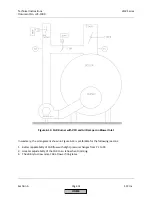
5.
To
find
the
wiring
issue
with
the
actuators
or
O
2
module,
plug
components
back
in
one
at
a
time
to
terminal
X51
on
the
LMV5
to
determine
which
component
is
causing
the
CANbus
errors.
First,
plug
in
just
the
cable
(unplugged
from
the
actuator)
that
connects
the
first
actuator
to
terminal
X51
on
the
LMV5.
Reset
the
fault
on
the
LMV5.
If
“Fault
Feedback
Air
Actuator”
shows
up
again,
the
cable
itself
is
okay.
Next,
plug
in
just
the
first
actuator
(unplugged
from
the
cable
running
to
the
second
actuator).
Reset
the
fault
on
the
LMV5.
As
long
as
actuator
feedback
faults
continue
to
show
up
after
each
component
is
plugged
in
and
the
LMV5
is
reset,
continue
to
plug
in
another
component.
At
some
point,
plugging
in
a
component
should
cause
the
CANbus
fault
to
recur.
6.
Once
the
component
causing
the
CANbus
errors
has
been
found,
check
the
following
to
correct
the
problem:
Make
sure
all
terminations
to
the
actuator
are
done
properly
and
no
wire
strands
from
adjacent
pins
are
touching
one
another
and
causing
a
short.
HOME
Summary of Contents for LMV 5 Series
Page 2: ...Intentionally Left Blank ...
Page 41: ...LMV Series Technical Instructions Document No LV5 1000 SCC Inc Page 7 Section 2 HOME ...
Page 42: ...Technical Instructions LMV Series Document No LV5 1000 Section 2 Page 8 SCC Inc HOME ...
Page 43: ...LMV Series Technical Instructions Document No LV5 1000 SCC Inc Page 9 Section 2 HOME ...
Page 44: ...Technical Instructions LMV Series Document No LV5 1000 Section 2 Page 10 SCC Inc HOME ...
Page 45: ...LMV Series Technical Instructions Document No LV5 1000 SCC Inc Page 11 Section 2 HOME ...
Page 46: ...Technical Instructions LMV Series Document No LV5 1000 Section 2 Page 12 SCC Inc HOME ...
Page 47: ...LMV Series Technical Instructions Document No LV5 1000 SCC Inc Page 13 Section 2 HOME ...
Page 48: ...Technical Instructions LMV Series Document No LV5 1000 Section 2 Page 14 SCC Inc HOME ...
Page 49: ...LMV Series Technical Instructions Document No LV5 1000 SCC Inc Page 15 Section 2 HOME ...
Page 50: ...Technical Instructions LMV Series Document No LV5 1000 Section 2 Page 16 SCC Inc HOME ...
Page 51: ...LMV Series Technical Instructions Document No LV5 1000 SCC Inc Page 17 Section 2 HOME ...
Page 52: ...Technical Instructions LMV Series Document No LV5 1000 Section 2 Page 18 SCC Inc HOME ...
Page 53: ...LMV Series Technical Instructions Document No LV5 1000 SCC Inc Page 19 Section 2 HOME ...
Page 54: ...Technical Instructions LMV Series Document No LV5 1000 Section 2 Page 20 SCC Inc HOME ...
Page 55: ...LMV Series Technical Instructions Document No LV5 1000 SCC Inc Page 21 Section 2 HOME ...
Page 373: ...Intentionally Left Blank ...