


Technical
Instructions
LMV
Series
Document
No.
LV5
‐
1000
Section
6
Page
34
SCC
Inc.
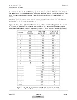
If
a
combustion
air
temperature
sensor
is
installed
and
activated,
the
air
temperature
will
be
recorded
when
the
last
point
is
entered
into
the
O
2
Control
Curve.
This
temperature
is
stored
under
the
following
menu
path:
Params
&
Display
>
O2Contr/Alarm
>
Gas/Oil
Settings
>
Startmode
>
Adjust.
Temp
O2
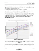
This
is
the
temperature
that
will
be
compared
against
the
current
air
temperature
to
perform
temperature
compensated
light
‐
off
if
parameter
StartMode
is
set
to
“IgnLoadTC”
or
“IgnPtWithTC”
(LMV52.440
only).
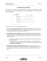
When
terminal
X5
‐
03.2
is
properly
configured
(see
Section
3
‐
Parameters),
it
can
be
energized
to
cause
a
deactivation
of
the
O
2
trim.
When
this
is
done,
the
LMV52
will
operate
on
the
O
2
Ratio
Control
Curve.
The
O
2
rich
and
lean
limits
will
be
active
as
long
as
there
is
a
valid
O
2
signal.
This
deactivation
via
X5
‐
03.2
occurs
without
a
notification
being
displayed
on
the
AZL52.
Pre
‐
purge
must
be
set
so
that
20.9%
(+/
‐
2.0%
O
2
)
is
read
by
the
QGO20
sensor.
If
this
is
not
met,
a
lockout
or
deactivation
will
occur
depending
on
the
setting
of
parameter
OptgMode
.
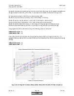
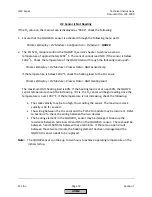
When
using
the
LMV52.440
on
low
or
ultra
‐
low
NOx
mesh
burners,
a
StartMode
of
“IgnPtWithTC”
is
typically
used
combined
with
adjusting
O2InitOffset
in
the
negative
direction
(more
rich).
If
done
properly,
this
should
make
the
transition
from
light
‐
off
position
to
low
fire
richer
than
normal
operation
so
that
the
transition
is
stable
and
reliable
under
varying
environmental
conditions.
While
the
burner
is
being
held
at
Point
2
awaiting
NumberTauSuspend
to
expire,
the
O2InitOffset
will
gradually
dissolve
and
the
%O
2
will
be
trimmed
to
setpoint
before
the
burner
is
released
to
modulate.
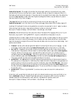
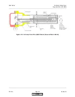
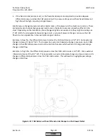
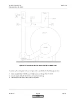
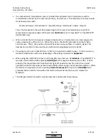
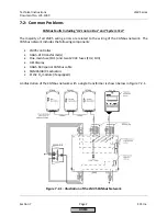
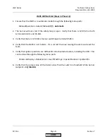
The
AGO
gas
collector
should
be
mounted
per
the
requirements
shown
below:
HOME
Summary of Contents for LMV 5 Series
Page 2: ...Intentionally Left Blank ...
Page 41: ...LMV Series Technical Instructions Document No LV5 1000 SCC Inc Page 7 Section 2 HOME ...
Page 42: ...Technical Instructions LMV Series Document No LV5 1000 Section 2 Page 8 SCC Inc HOME ...
Page 43: ...LMV Series Technical Instructions Document No LV5 1000 SCC Inc Page 9 Section 2 HOME ...
Page 44: ...Technical Instructions LMV Series Document No LV5 1000 Section 2 Page 10 SCC Inc HOME ...
Page 45: ...LMV Series Technical Instructions Document No LV5 1000 SCC Inc Page 11 Section 2 HOME ...
Page 46: ...Technical Instructions LMV Series Document No LV5 1000 Section 2 Page 12 SCC Inc HOME ...
Page 47: ...LMV Series Technical Instructions Document No LV5 1000 SCC Inc Page 13 Section 2 HOME ...
Page 48: ...Technical Instructions LMV Series Document No LV5 1000 Section 2 Page 14 SCC Inc HOME ...
Page 49: ...LMV Series Technical Instructions Document No LV5 1000 SCC Inc Page 15 Section 2 HOME ...
Page 50: ...Technical Instructions LMV Series Document No LV5 1000 Section 2 Page 16 SCC Inc HOME ...
Page 51: ...LMV Series Technical Instructions Document No LV5 1000 SCC Inc Page 17 Section 2 HOME ...
Page 52: ...Technical Instructions LMV Series Document No LV5 1000 Section 2 Page 18 SCC Inc HOME ...
Page 53: ...LMV Series Technical Instructions Document No LV5 1000 SCC Inc Page 19 Section 2 HOME ...
Page 54: ...Technical Instructions LMV Series Document No LV5 1000 Section 2 Page 20 SCC Inc HOME ...
Page 55: ...LMV Series Technical Instructions Document No LV5 1000 SCC Inc Page 21 Section 2 HOME ...
Page 373: ...Intentionally Left Blank ...