
LMV Series
Technical Instructions
Document No. LV5-8000
SCC Inc.
Page 11
Appendix A
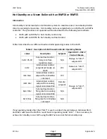
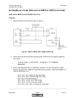
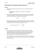
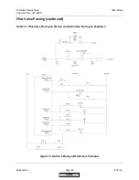
Hot Standby on a Steam Boiler with an RWF50 or RWF55 (continued)
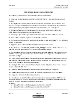
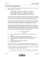
4.
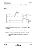
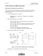
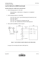
Set the following parameters in the RWF55 controller. For more information, obtain
Siemens Document No. U7867 for the RWF55 at www.scccombustion.com.
ConF > Cntr > CtYP = 2
ConF > Cntr > SPL = setpoint range lower limit
ConF > Cntr > SPH = setpoint range upper limit
OPr > SP1 = normal operation setpoint
PArA > HYS1 = burner on for normal operation
PArA > HYS3 = burner off for normal operation
ConF > InP > InP1 > Sen1 = pressure sensor type
ConF > InP > lnP1 > SCL1 = 0
ConF > InP > InP1 > SCH1 = high end of the range of the pressure sensor
ConF > InP > InP3 > Sen3 = temperature sensor type
ConF > AF > FnCt = 12
ConF > AF > AL = hot standby setpoint
ConF > AF > HYSt = burner on / off for hot standby
ConF > OutP > SiGn = 2
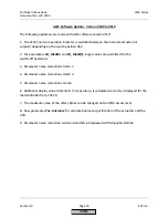
Operation
1.
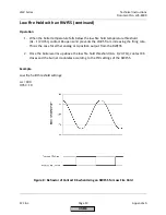
When the hot standby switch is set for hot standby, the LMV5 system is in hot standby
mode. The burner will turn on and off based on the temperature limits set in the
RWF55 controller for hot standby (ConF > AF). Since the signal to LMV5 terminal X62 is
broken by the hot standby switch, the LMV5 stays at low fire until the burner turns off
based on the burner off point set in the RWF55.
2.
When the hot standby switch is set for normal operation, the system is in normal
operation mode and not in hot standby. The burner will turn on and off based on the
pressure limits set in the RWF55 controller for normal operation (PArA > HYS1 and PArA
> HYS3). The signal to LMV5 terminal X62 determines the firing rate of the burner.
Important Notes
1.
An RWF55 controller must be used for this hot standby option (not RWF50).
2.
The RWF55 is operating as the load controller during normal operation as well as
controlling the hot standby.
HOME
Summary of Contents for LMV 5 Series
Page 2: ...Intentionally Left Blank ...
Page 41: ...LMV Series Technical Instructions Document No LV5 1000 SCC Inc Page 7 Section 2 HOME ...
Page 42: ...Technical Instructions LMV Series Document No LV5 1000 Section 2 Page 8 SCC Inc HOME ...
Page 43: ...LMV Series Technical Instructions Document No LV5 1000 SCC Inc Page 9 Section 2 HOME ...
Page 44: ...Technical Instructions LMV Series Document No LV5 1000 Section 2 Page 10 SCC Inc HOME ...
Page 45: ...LMV Series Technical Instructions Document No LV5 1000 SCC Inc Page 11 Section 2 HOME ...
Page 46: ...Technical Instructions LMV Series Document No LV5 1000 Section 2 Page 12 SCC Inc HOME ...
Page 47: ...LMV Series Technical Instructions Document No LV5 1000 SCC Inc Page 13 Section 2 HOME ...
Page 48: ...Technical Instructions LMV Series Document No LV5 1000 Section 2 Page 14 SCC Inc HOME ...
Page 49: ...LMV Series Technical Instructions Document No LV5 1000 SCC Inc Page 15 Section 2 HOME ...
Page 50: ...Technical Instructions LMV Series Document No LV5 1000 Section 2 Page 16 SCC Inc HOME ...
Page 51: ...LMV Series Technical Instructions Document No LV5 1000 SCC Inc Page 17 Section 2 HOME ...
Page 52: ...Technical Instructions LMV Series Document No LV5 1000 Section 2 Page 18 SCC Inc HOME ...
Page 53: ...LMV Series Technical Instructions Document No LV5 1000 SCC Inc Page 19 Section 2 HOME ...
Page 54: ...Technical Instructions LMV Series Document No LV5 1000 Section 2 Page 20 SCC Inc HOME ...
Page 55: ...LMV Series Technical Instructions Document No LV5 1000 SCC Inc Page 21 Section 2 HOME ...
Page 373: ...Intentionally Left Blank ...